background image

Page 6 - 

51033776EN/AA

2. Installation

L +

BA
TTERIE/BA

TTER

Y

L -

4

2

25A

t

In

B

1

10

90

20

3

25A

12V-65Ah

5

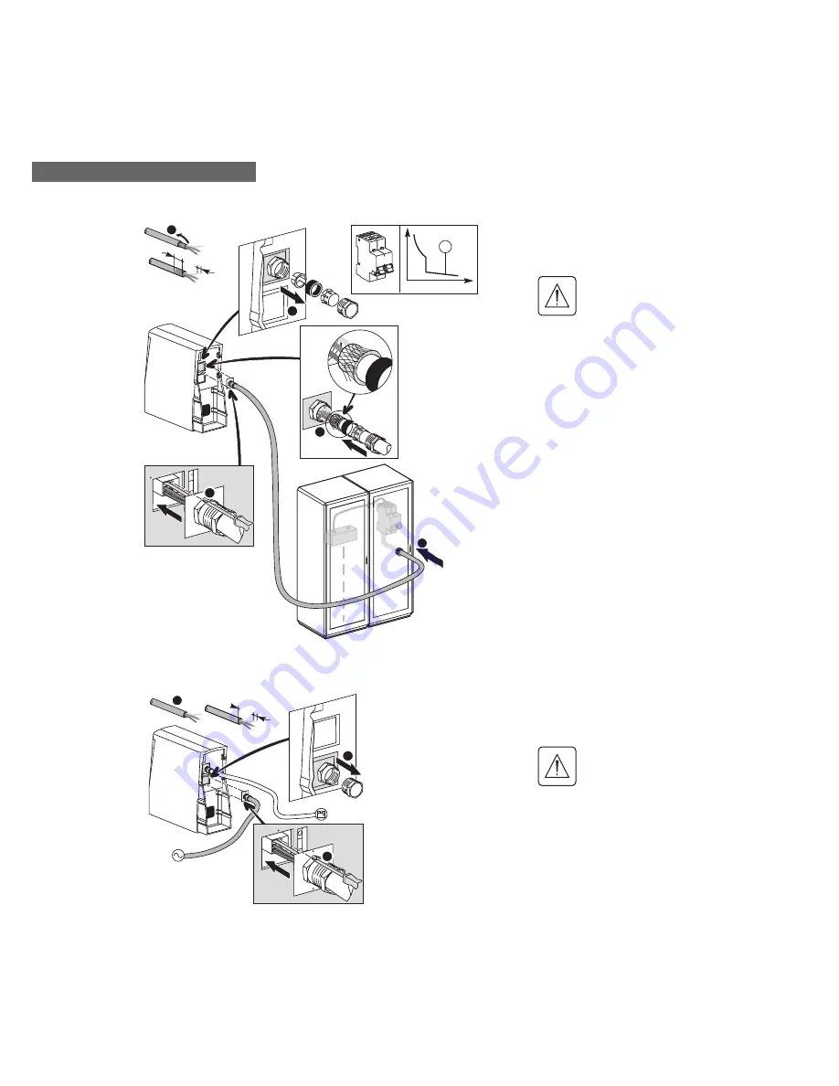
Use a 3-conductor cable (shielded, max.
length 6 m, 3 x 4 mm

2

 conductors) to be

passed through the shielded cable gland.

Use a 25 A circuit breaker
(curve B) for protection.

Note: 

the cable and circuit breaker are not

supplied with the product.

1. Prepare the cable.

2. Unscrew the plate and dismantle the
metal cable gland on the 

Comet EX

treme

CLA

 module.

3. Mount the cable gland on the shielded
cable.

4. Connect the 3 conductors to the terminal
block and refit the plate.

5. Connect the other end of the cable to the
circuit breaker.

2.5 Connecting the Comet EX

treme

 CLA module to the power source

10

50

1

L +

RESEA

U/MAINS/NETZ

N

3

2

+

Use a flexible cable (3 x 2.5 mm

2

conductors) to be passed through the plastic
cable gland.

Always connect the earth wire
first. Use a 10 A circuit breaker
(curve C) for protection.

Note:

 the cable and circuit breaker are not

supplied with the product.

1. Prepare the cable.

2. Unscrew the plate with the plastic cable
gland.

3. Connect the 3 conductors and remount
the plate.

Summary of Contents for Comet EXtreme CLA

Page 1: ...51033776EN AA Page 1 www mgeups com MGE UPS SYSTEMS Comet EXtreme CLA 6 kVA Installation manual N O T H I N G W I L L S T O P Y O U N O W...

Page 2: ...Page 2 51033776EN AA...

Page 3: ...age 3 and checking the contents 1 Unpacking Comet EXtreme CLA 6 kVA Tower model Rack model Comet EXtreme CLA module connection cable 1 2 documentation telescopic rails and 19 rack mounting hardware 3...

Page 4: ...Page 4 51033776EN AA Mounting the rails in the rack The rails and the screws required to mount them are included in the box 2 1 Mounting Rack model 2 Installation 1 2 3 3 3 3 4...

Page 5: ...t breaker Before making any connections or working on the equipment make sure the battery circuit breaker is in OFF position and that the main contacts of the upstream protective devices of the electr...

Page 6: ...ule 3 Mount the cable gland on the shielded cable 4 Connect the 3 conductors to the terminal block and refit the plate 5 Connect the other end of the cable to the circuit breaker 2 5 Connecting the Co...

Page 7: ...the battery circuit breaker to ON position 2 Connect a PC to the UPS using an RS232 cable 3 Run the UPS Driver software installed on a diskette Go to the battery menu and select the battery backup ti...

Page 8: ...LA 4 hr CLA 8 hr CLA 2 hrs 30 min 5 hrs 40 min 9 hrs 3 hrs 20 min 7 hrs 30 min 13 hrs 40 min 5 hrs 20 min 13 hrs 40 min 21 hrs Recharge time to 90 full backup time 2 hr CLA 9 hrs 4 hr CLA 8 hr CLA 15...

Page 9: ...5103377600 AA...

Page 10: ...5103377600 AA MGE UPS SYSTEMS 140 Avenue Jean Kuntzmann ZIRST Montbonnot St Martin 38334 Saint Ismier Cedex France www mgeups com Nothing will stop you now 5103377600 AA...

Reviews: