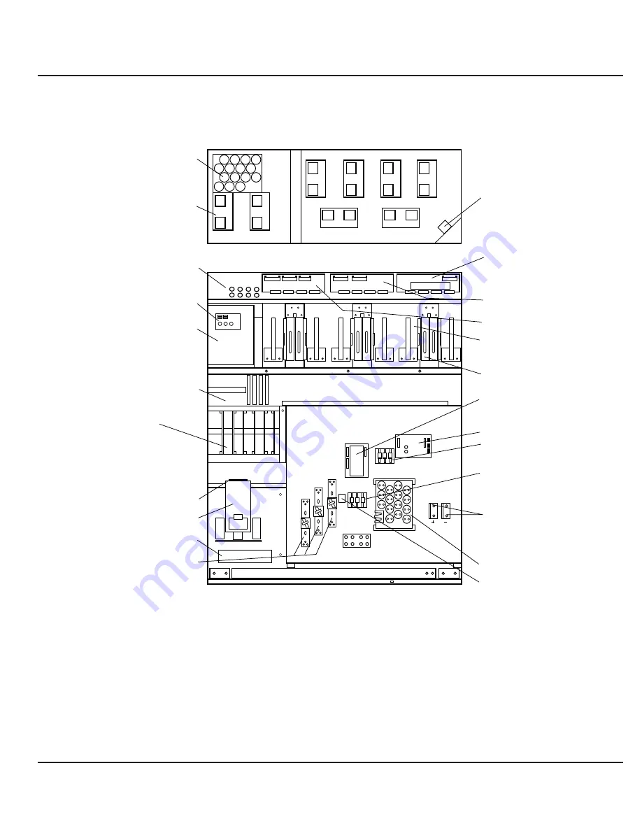
Figure
E P S 6 0 0 0 M a j o r I n t e r n a l C o m p o n e n t s ,
1-16
S h a r e d 5 0 0 k VA U P S M o d u l e , U P S C a b i n e t
FRONT VIEW, DOORS AND COVERS REMOVED
TOP VIEW, COVER REMOVED
AC CAP ASSY.
K1
BATTERY
CONNECTION
(OPTIONAL)
F10,F11,F18,F19
F12,F13
DELAY
ALBZ
APOZ
INVERTERS (x6)
DC CAPACITERS
(BEHIND EACH INVERTER)
RAUZ
OBEZ
IBEZ
FAN
TRANSFORMER
OUTPUT FUSES
F7, F8, F9
K3N
STATIC SWITCH
K3NZ
1- GTCZ PCA
2- SRIZ PCA
3- CRIZ PCA
4- CROZ / DO6Z PCA
5- AROZ PCA
6- ALEZ PCA
CARD CAGE:
AC OUTPUT
CAPACITORS
CHARGER & TREZ
(BEHIND PLATE)
EPOZ
FB1 TO FB8
AC CAPACITOR
ASSEMBLY
FANS
(x 8)
6
6
5
NEUTRAL
4
3
2
1
1 2 3 4 5 6
5
4
3
7
8
1
2
1 — 16
Introduction
EPS 6000 Uninterruptible Power System
Summary of Contents for EPS 6000
Page 1: ...EPS 6000 UPS Uninterruptible Power Systems Installation Manual...
Page 10: ...this page left blank intentionally EPS 6000 Uninterruptible Power System...
Page 40: ...this page left blank intentionally EPS 6000 Uninterruptible Power System...
Page 50: ...this page left blank intentionally EPS 6000 Uninterruptible Power System...
Page 70: ......
Page 71: ......


