


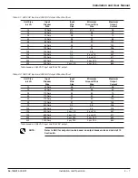

1.3
Receiving and Inspection Notes
Before accepting the shipment from the freight carrier, inspect the exterior surfaces of all shipping containers or
packaging used, and the equipment, for damage that may have occurred during transit. If the shipping containers
or equipment shows evidence of damage, note the damage on the receiving document (bill of lading) prior to signing
for receipt of equipment.
ALL CLAIMS FOR SHIPPING DAMAGE MUST BE FILED DIRECTLY WITH THE CARRIER. Replacements for
damaged components should be ordered through MGE UPS SYSTEMS.
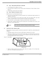
Check by thorough inspection if any electrical connections have become loose because of vibration during
shipment. Remove top and side panels (Not applicable on 225kVA and larger).
Check the nameplate to be sure that the voltage and frequency match the available power supply. Under no circum-
stance should the unit be connected to a power source which does not conform to the nameplate rating.
1.3.1
Location and Storage
The unit has been completely inspected and extensively tested under various load conditions prior to shipment.
Care to install it at a proper location will assure long trouble free operation. The unit is forced air cooled with the air
intake at the bottom, front or sides and exhausts out at the top or rear. Therefore, it should be installed in a clean,
dry place with enough clearance to allow a free flow of air.
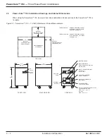
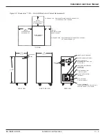
Allow at least 4 inches of space between the unit and the wall or other equipment for portable units.
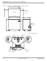
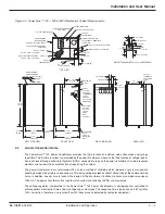
Allow enough space for maintenance as indicated on the cabinet outlines. See Section 2.0, Figures 2-1 thru 2-4. If
the equipment is to be stored prior to installation, it should be stored in a cool, dry, well-ventilated location that is
protected from rain, splashing water, chemical agents, etc. The equipment should be covered with a tarpaulin or
plastic wrapper to protect it against dust, dirt, paint, or other foreign materials.
1.4
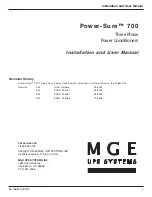
General Description
The Power-Sure™ 700 is a continuous duty power conditioner designed to supply reliable, clean regulated power to
critical loads. An efficient design with state of the art micro-processor controlled solid state devices provide immunity
to all line disturbances. The cabinet is a heavy gauge industrial steel throughout. Metal is anti-corrosive phosphate
treated prior to paint. Paint is a baked finish.
The basic design consists of a three phase triple shielded isolation transformer with seven separate voltage taps
per phase. Output regulation is achieved by monitoring the input and automatically switching taps anytime the input
line sags or surges. The use of a triple shielded isolation transformer provides superior common mode and trans-
verse mode noise attenuation. Automatic switching occurs during current zero allowing noise free switches for both
leading and lagging power factor loads that are connected to the Power-Sure™ 700.
The Power-Sure™ 700 Power Conditioner is operated by simply turning on the main AC input circuit breaker. As an
option, units may have a bypass switch. This is a no load switch and MUST only be operated when the unit is OFF.
The bypass switch should be in the “NORMAL” position unless a problem occurs with the system. If a problem
occurs, turn OFF the main AC circuit breaker and turn the bypass switch to the “BYPASS” position. Re-energize the
system by turning on the AC circuit breaker and contact the Customer Care Center for repairs.
Any ‘ALERT” condition requires the main AC input breaker to be turned off in order to reset the “ALERT” light.
Introduction - Description
Power-Sure™ 700 —
Three Phase Power Conditioners
1 — 2
86-108814-00 B01


