background image


51031604EN/AB

 - Page 19

3. Operation

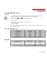
3.4 Personalisation 

(optional)

Function

Personalisable function

Automatic start

Cold start (battery power)

Forced shutdown

Sleep mode

UPS ON / OFF via software

Default setting

Enabled

Enabled

Enabled

Disabled

Enabled

Personalisation parameters can be set and modified using the "UPS Driver" software installed on a computer that is
connected to the UPS (see section 2.3 Connection to the RS 232 (or USB) communications port).

Check that the RS 232  25  or USB  26  cable is properly connected.

"UPS Driver" installation:

1 - Insert the "UPS Driver" diskette in the drive of a PC running Windows.
2 - Select the disk drive (A:\).
3 - Double-click "upsdriv.exe".

Once "UPS Driver" has been installed, UPS parameters can be modified in a window containing a number of tabs, each
presenting a set of parameters.

"ON / OFF conditions" tab

"Battery" tab

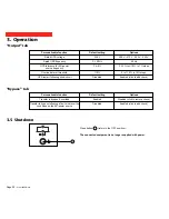
Personalisable function

Automatic "Battery test" intervals

"Low-battery warning" threshold

Default setting

Every day

20% remaining battery backup time

Options

Once a week

Once a month

No test

40% remaining battery backup time

Options

Disabled

Disabled

Disabled

Enabled

Disabled

Summary of Contents for Pulsar EX 1000

Page 1: ...51031604EN AA Page 1 Installation and user manual Pulsar EX 700 1000 1500...

Page 2: ...our UPS MGE UPS SYSTEMS pays great attention to the environmental impact of its products Measures that have made Pulsar EX a reference in environmental protection include the eco design approach used...

Page 3: ...andling Product safety UPSs must be connected to a nearby wall outlet that is easily accessible The UPS can be disconnected from the AC power source by removing the power cord Never install the UPS ne...

Page 4: ...at must always be followed Information advice help Visual indication Action Audio indication In the illustrations on the following pages the symbols below are used LED off LED on LED flashing Informat...

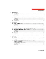
Page 5: ...rack version 13 2 3 Connection to the RS 232 or USB communications port optional 14 2 4 Installation of the communications card option 15 Tower model 15 Rack model 15 2 5 Connections 16 Tower model 1...

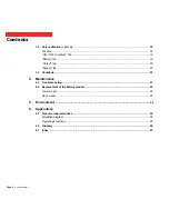
Page 6: ...ttery tab 19 Output tab 20 Bypass tab 20 3 5 Shutdown 20 4 Maintenance 4 1 Troubleshooting 21 4 2 Replacement of the battery module 22 Tower model 22 Rack model 23 5 Environment 24 6 Appendices 6 1 Te...

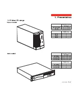
Page 7: ...X 700 EX 1000 EX 1500 Dimensions in mm H x W x D 235 5 x 145 x 400 235 5 x 145 x 505 Weight in kg 10 12 15 EX 700 Rack EX 1000 Rack EX 1500 Rack EX 700 Rack EX 1000 Rack EX 1500 Rack Dimensions in mm...

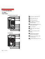
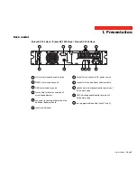
Page 8: ...n of protected equipment connector for automatic detection of an additional battery module input circuit breaker socket for connection to AC power source connector for an additional battery module pus...

Page 9: ...ort four outlets for direct connection of protected equipment connector for automatic detection of an additional battery module input circuit breaker 1 2 3 4 5 6 7 9 8 10 11 socket for connection to A...

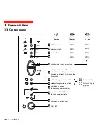
Page 10: ...ass and back by pressing button 3 times in less than 5 seconds status of programmable outlet 1 operation on bypass no backup power available operation in ON LINE mode backup power available ON OFF bat...

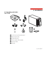
Page 11: ...king and checks two cords for connection of the protected equipment RS 232 communications cable USB communications cable UPS Driver diskette for UPS personalisation Solution Pac CD ROM documentation 2...

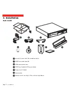
Page 12: ...ck 24 two cords for connection of the protected equipment 25 RS 232 communications cable 26 USB communications cable 27 UPS Driver diskette for UPS personalisation 28 Solution Pac CD ROM 29 documentat...

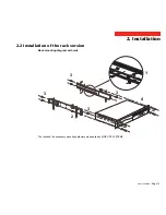
Page 13: ...04EN AA Page 13 2 2 Installation of the rack version 2 Installation Rack mounting diagram with rails The rails and the necessary mounting hardware are supplied by MGE UPS SYSTEMS 1 2 3 3 3 3 4 EX1 000...

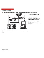
Page 14: ...e to the serial port or the USB port on the computer 2 Connect the other end of the communications cable 25 or 26 to the RS 232 2 or USB 3 communications port on the UPS The UPS can now communicate wi...

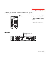
Page 15: ...to shut down the UPS to install the communications card 1 Remove the slot 1 cover secured by two screws 2 Insert the card in the slot 3 Secure the card with the two screws Tower model Rack model Slot...

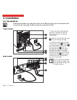
Page 16: ...ocket 7 then to the AC power wall outlet 3 Connect the protected equipment to the UPS using the two cords 24 It is advised to connect priority loads to the four outlets 4 and any non priority loads to...

Page 17: ...ere is a fault see section 4 1 3 2 Bargraph indications LEDs 12 to 15 provide three different indications 1 Remaining backup time in percent during normal operation 2 Percent load drawn by the protect...

Page 18: ...he buzzer beeps every three seconds There is very little remaining battery backup time Close all applications because UPS automatic shutdown is imminent End of backup time The buzzer sounds continuous...

Page 19: ...that the RS 232 25 or USB 26 cable is properly connected UPS Driver installation 1 Insert the UPS Driver diskette in the drive of a PC running Windows 2 Select the disk drive A 3 Double click upsdriv...

Page 20: ...210 V 220 V 240 V 60 Hz F 1 to 10 in 1 steps 0 to 110 in 10 steps Enabled click to add check Personalisable function Transfer to bypass if overload Transfer to bypass following a fault whatever the co...

Page 21: ...f your electrical network has detected a reversal Correction Check the power drawn by the equipment and disconnect any non priority devices Check that the battery connector is fully pushed in Replace...

Page 22: ...ult Depending on the UPS personalisation parameters see section 3 4 there are two possibilities the equipment connected to the UPS continues to be supplied but directly from the AC power source via th...

Page 23: ...itute a danger electrical shock burns The short circuit current may be very high Precautions must be taken for all handling remove all watches rings bracelets and any other metal objects use tools wit...

Page 24: ...y module in place D Remove the bar E Disconnect the battery module F Remove the battery module Reinstallation of the battery module Carry out the above operation in reverse order To maintain an identi...

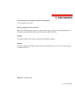
Page 25: ...mpanies and in compliance with all applicable regulations all UPS products recovered at the end of their service life contact your MGE branch office Packing UPS packing materials must be recycled in c...

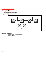
Page 26: ...Page 26 51031604EN AB 6 Appendices 6 1 Technical characteristics Operating conditions Relative humidity 20 to 90 without condensation Temperature 0 to 40 C Simplified diagram...

Page 27: ...rsion The power supplied to the connected equipment is completely regenerated by continuous double conversion i e the AC power from the AC power source is rectified AC DC then converted back DC AC to...

Page 28: ...15 Connection Additional battery module 8 9 Communications card 14 RS 232 communications port 14 USB communications port 14 D Dimensions 7 E Environnement 2 3 24 F Fault UPS 10 17 21 22 L LEDs 8 9 10...

Reviews: