3.2.1
Normal Start Up Procedure
With all of the initial safety check points verified, the Epsilon STS™ system can now be powered. The following
procedure should be used after the Epsilon STS™ system has been commissioned (typically by an MGE Field
Service Engineer).
1.
Ensure that all switches, CB1, 2, 3A, 3B(if installed), 4 and 5 in the STS are OFF (open).
2.
Energize both input sources and check for correct voltage, phase rotation and source synchronization. The
STS controls will be powered up and the display LCD should turn on. The LED indicators and mimic diagram
should also be functioning. The display and buzzer may indicate an alarm since the source isolation switches,
CB1 and CB2 are open.
3.
If external load circuit breaker(s) are not installed between the STS output and the load, check that the load is
ready for power application.
4.
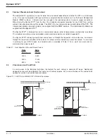
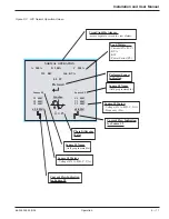
Check that Source #1 is the preferred source (factory default setting) – as indicated on the LCD display and the
“Preferred Source S1” LED located in the mimic diagram.
5.
Close the Source #1 bypass switch, CB4, which connects the output to Source #1, bypassing the static switch
section. Output is now energized by Source #1. The bypass switches are interlocked – see note.
NOTE
CB4 and CB5 bypass switches are key-interlocked.
The standard 2-interlock system, lock the opposite bypass
switch and remove the key (for the optional 4-interlock system,
it is also necessary to open the opposite source isolation
switch (CB1 or CB2), lock it, remove the key). Using the
removed key(s), unlock and close the selected bypass switch.
6.
Apply power to the load by closing the load-circuit beakers (if installed), including PMM power distribution circuit
beakers (where applicable).
7.
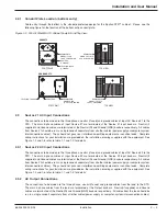
Close the Source #1 (preferred) isolation switch, CB1. The STS will turn on the preferred source SCR Switch
1. Verify on the LED mimic diagram on the front display panel. Also check the operating status on the LCD screen.
8.
Close the Source #2 (alternate) isolation switch, CB2. Verify on the LED mimic diagram on the front display
panel. Also check the operating status on the LCD screen – no alarms should be displayed.
9.
Static switch operation may now be checked by opening the preferred source isolation switch, CB1. The STS
will transfer to the alternate source. Verify on the LED mimic diagram on the front display panel. Also check
the operating status on the LCD screen.
10. Re-close the preferred source isolation switch, CB1. After the preset retransfer time delay, the STS will retransfer
back to the preferred Source #1.
11. Close the STS output isolation switch(es), CB3A (and CB3B if installed). Source #1 power is now supplied
through the static switch to the output of the STS.
12. Open (and lock) the Source #1 bypass switch, CB4. The load is now supplied through the static switch. Verify
on the LED mimic diagram on the front display panel. Also check the operating status on the LCD screen.
13. The STS is now in the normal operating mode:
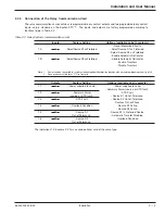
CB1, CB2, CB3A and CB3B(if installed) - CLOSED.
CB4 AND CB5 - OPEN
LCD screen - Normal Operation
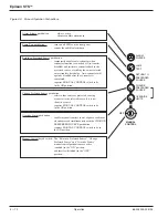
LED Mimic diagram - “Source S1 Available”, “Source S2 Available”, “CB1”, “CB2”, “Switch 1”, “CB3”, “Load”
and “In Sync” LED's on.
Epilson STS
TM
Operation
3 —2
86-504004-00 B03
Summary of Contents for STS 400A
Page 2: ......
Page 28: ... This page left blank intentionally Epilson STSTM 1 12 86 504004 00 B02 ...
Page 54: ... This page left blank intentionally Product Name 3 16 86 504004 00 B02 ...
Page 58: ... This page left blank intentionally Product Name W 4 86 504004 00 B02 ...
Page 62: ... This page left blank intentionally Epilson STSTM G 4 86 504004 00 B03 ...
Page 64: ......
Page 65: ......


