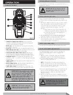
Lawn Tractor Rear Discharge
33
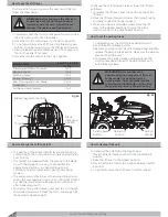
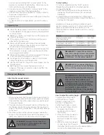
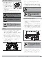
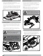
The tension of the belt can be adjusted with the adjustment
nut as indicated in (Fig 49), by following these next steps:
1. Loosen the nut under the pulley by rotating it
anti-clockwise.
2. Adjust the tension of the belts as required.
3. Tighten the nut under the pulley accordingly.
1. Check the chain tension after setting the drive
conversion unit to the highest gear.
2. Adjust the drive conversion unit while the engine is
operating in minimal number of revolutions and the
travel lever being in the neutral position “N”.
3. After turning the engine off, check the chain tension
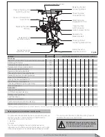
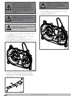
and when necessary loosen the nut (2 – Fig 51)
4. With the adjusting screw set the chain tension.
5. Once complete, tighten the nut accordingly.
6. Do this adjustment with the disassembled throat of
the rear plate.
Adjusting the drive belt of the blades drive
Adjusting the chain
IMPORTANT:
It is recommended that your
authorized service centre makes these belt
adjustments.
WARNING:
Wear strong gloves when
handling the blades.
Fig 49
Adjustment
Nut
Adjusting the drive conversion unit belt
The operation of the drive conversion unit is ensured by a
belt between the engine and central conversion unit pulley.
Adjust the right position and tension of the belt if the belt
is slipping or the belt tension is wrong while pushing the
brake pedal down.
$IWHUWKHULJKWDGMXVWPHQWWKHEHOWRQWKH´UVWJHDULV
3mm below the outside periphery of the central
conversion pulley.
7KHFKDQJHLQWKH´UVWJHDULVWREHGRQHGXULQJPLQLPDO
number of engine revolutions.
3. Transfer the travel lever from the neutral position “N’ in
WKHSRVLWLRQRIWKH´UVWJHDU
4. Check and adjust the belts while the engine is being
turned off.
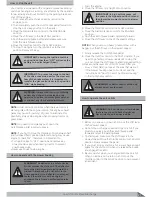
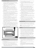
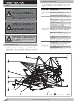
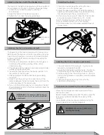
5. Adjust it with the nut (Fig 50). Loosen the nut if the
distance between the belt is smaller than 3 mm from the
outside periphery of the central pulley.
6. If you turn the central pulley by two revolutions the belt
should displace by 2mm. After this adjustment check the
belt position again.
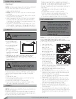
1. The initial tension of the spring (3 – Fig 51) can be
reduced by prolonging the belts.
2. Adjust the initial tension with the nut (4 – Fig 51) you
´QGDIWHUWDNLQJRIIWKHFRQWDLQHURIWKHUHDUSODWH
3. Set the spring so that the limiting chain (5 – Fig 51) is
going to be tightened up completely while the engine
is operating.
4. Check the chain tension once more after the
adjustment of the spring.
Adjusting the drive conversion unit spring
&KHFNWKDWWKHEODGHVDUHZHOOVKDUSHQHGDQG´UPO\
´[HGWRWKHLUKXEV
Badly sharpened blades will pull at the grass, cause the
lawn to turn yellow and reduce the capacity of the
container.
Loose blades will cause unusual vibrations during the
mowing operation and can be dangerous.
Sharpening and balancing the cutting blades
3mm
Fig 50
Fig 51
3
4
2
1
5
Summary of Contents for Gizmow T130
Page 12: ...KNOW YOUR PRODUCT Lawn Tractor Rear Discharge 12 Decals and Labels ...
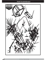
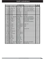
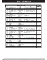
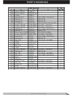
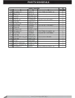
Page 37: ...PARTS SCHEDULE Lawn Tractor Rear Discharge 37 T130 T140 T160 T180 Lawn Tractor Rear Discharge ...
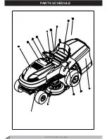
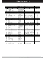
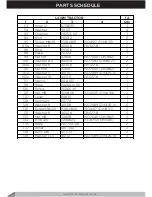
Page 38: ...PARTS SCHEDULE Lawn Tractor Rear Discharge 38 ...
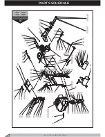
Page 40: ...Lawn Tractor Rear Discharge 40 PARTS SCHEDULE T130 T160 T140 T180 LAWN TRACTOR 1A ...
Page 44: ...T130 T160 T140 T180 LAWN TRACTOR 1B PARTS SCHEDULE Lawn Tractor Rear Discharge 44 ...
Page 49: ...T130 T160 LAWN TRACTOR 1C Lawn Tractor Rear Discharge 49 PARTS SCHEDULE ...
Page 50: ...T140 T180 LAWN TRACTOR 1C PARTS SCHEDULE Lawn Tractor Rear Discharge 50 ...
Page 53: ...T130 T160 T140 T180 LAWN TRACTOR 1D Lawn Tractor Rear Discharge 53 PARTS SCHEDULE ...
Page 56: ...T130 T160 T140 T180 CUTTING DECK 2 PARTS SCHEDULE Lawn Tractor Rear Discharge 56 ...
Page 60: ...T130 T160 FRONT AXLE 7 PARTS SCHEDULE Lawn Tractor Rear Discharge 60 ...
Page 61: ...T140 T180 FRONT AXLE 7 Lawn Tractor Rear Discharge 61 PARTS SCHEDULE ...
Page 63: ...T130 T160 T140 T180 LIFTING LEVER 11 Lawn Tractor Rear Discharge 63 PARTS SCHEDULE ...
Page 65: ...T130 T160 T140 T180 HUB 14 Lawn Tractor Rear Discharge 65 PARTS SCHEDULE ...
Page 67: ...T130 T160 T140 T180 REAR AXLE 15A Lawn Tractor Rear Discharge 67 PARTS SCHEDULE ...
Page 69: ...T130 T160 T140 T180 REAR AXLE 15B Lawn Tractor Rear Discharge 69 PARTS SCHEDULE ...
Page 73: ...T130 T160 T140 T180 HOOD 24 Lawn Tractor Rear Discharge 73 PARTS SCHEDULE ...
Page 75: ...T130 T160 T140 T180 PANEL 25 Lawn Tractor Rear Discharge 75 PARTS SCHEDULE ...
Page 77: ...T130 T160 T140 T180 ELECTRICAL SYSTEM 27 Lawn Tractor Rear Discharge 77 PARTS SCHEDULE ...
Page 78: ...T130 T160 T140 T180 ELECTRICAL SYSTEM 27a PARTS SCHEDULE Lawn Tractor Rear Discharge 78 ...
Page 80: ...T130 T160 T140 T180 SEAT 32 PARTS SCHEDULE Lawn Tractor Rear Discharge 80 ...
Page 82: ...T130 T160 T140 T180 BUNKER 34 PARTS SCHEDULE Lawn Tractor Rear Discharge 82 ...
Page 84: ...T130 T160 T140 T180 GEAR SHIFTING 35 PARTS SCHEDULE Lawn Tractor Rear Discharge 84 ...
Page 86: ...T130 T160 T140 T180 SEGMENT 36 PARTS SCHEDULE Lawn Tractor Rear Discharge 86 ...
Page 88: ...T130 T160 T140 T180 PLATE 37 PARTS SCHEDULE Lawn Tractor Rear Discharge 88 ...
Page 90: ...T130 T160 T140 T180 DECALS 38 PARTS SCHEDULE Lawn Tractor Rear Discharge 90 ...

