background image

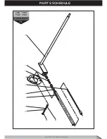
T130   T160
T140   T180

LAWN TRACTOR

1D

Lawn Tractor Rear Discharge

53

PARTS SCHEDULE

Summary of Contents for Gizmow T130

Page 1: ...SAVE THIS MANUAL FOR FUTURE REFERENCE Gizmow T130 Gizmow T140 Gizmow T160 Gizmow T180 Lawn Tractor Rear Discharge Operator s Manual ...

Page 2: ...Q µDPHV 10 Trouble Shooting 35 3DUWV 6FKHGXOH 37 Notes 97 10 10 Max Max 0DFKLQH 5ROORYHU Do not use this machine on slopes greater than 10 LVPHPEHUPHQW Make sure that children stay clear of the machine all the time when engine is running Disconnect the ignition key and read the instructions before carry out any repair and maintenance work Do not operate without either the stone guard or grass catc...

Page 3: ...y read and follow the rules for safe operation Follow all the assembly instructions Inspect the unit Make sure that the operator of the unit knows how to correctly use all standard and accessory equipment Operate the unit only with guards shields and other safety items in place and working correctly Correctly adjust the unit Service the unit only with authorized or approved replacement parts Compl...

Page 4: ...g Height 3 9 cm Number of Cutting Heights 7 Grass Collector Capacity 300L Fuel Type Unleaded Regular Turning Radius 75 cm 33005 T140 257 kg 150 kg Briggs Stratton Intek AVS OHV 13 5 HP 4 Stroke Yes 7L Appr 48oz 1 42L SAE30 SAE5W 30 12V 24 Ah DC regulated Part NO 5066 98 dB Yes 7 R 2 2 9 2 km h 4 6 km h 15 x 6 00 6 18 x 8 50 8 1 4 Bar 1 0 Bar 2 102 cm 3 9 cm 7 300L Unleaded Regular 75 cm 33010 T160...

Page 5: ...e storage DANGER THIS CUTTING MACHINE IS CAPABLE OF AMPUTATING HANDS AND FEET AND THROWING OBJECTS FAILURE TO OBSERVE THE FOLLOWING SAFETY INSTRUCTIONS COULD RESULT IN SERIOUS INJURY OR DEATH Safe Operation Practices for Ride On Machines WARNING In order to prevent accidental starting when setting up transporting adjusting or making repairs always disconnect spark plug wire and place wire where it...

Page 6: ...ther ride and be run over or backed over by the machine Keep children out of the mowing area and in the watchful care of a responsible adult other than the operator Be alert and turn machine off if a child enters the area Before and while backing look behind and down for small children Mow up and down slopes 10 Max not across Choose a low ground speed so that you will not have to stop or shift whi...

Page 7: ...ipment must learn to use correct and safe mowing procedures To help you learn carefully read the following pages Most of the time the operator was not correctly shown or did not read the instructions on the unit or in the Instruction Manual before using the unit Also some operators do not have enough experience The result is unsafe use endangering the operator bystanders and the equipment Another ...

Page 8: ...y gasoline from the outside of the fuel tank or from the mower Warm gasoline will expand Leave some space in the fuel tank for the gasoline to expand Also the fuel cap has a vent hole for fuel vapors Always use the correct fuel cap Failure to IROORZ VDIHW UXOHV DERXW JDVROLQH ZLOO FDXVH UHV DQG explosions injury to you and damage to the equipment and other property If you add gasoline to an engine...

Page 9: ... stopped always disconnect the wire from the spark plug to prevent the engine from starting If you hit a large object during operation stop the engine Remove the wire from the spark plug Carefully inspect the mower for damage Before you start the engine again make the necessary repairs If you feel QHZ RU H FHVVLYH YLEUDWLRQ LPPHGLDWHO VWRS WKH HQJLQH and check for the problem Vibration can be a wa...

Page 10: ... b Brake Engaged 10 Cutting Height Adjusting Lift Lever This lever allows you to adjust the blade height to seven positions which range from 3cm 9cm 11 Cutting Deck This is the guard which encloses and covers the rotating blades 12 Cutting Blades These are components which cut the grass Specially designed wings at the ends help push the cut grass towards the collector channel 13 Collector Channel ...

Page 11: ...Lawn Tractor Rear Discharge 11 KNOW YOUR PRODUCT Illustrated Drawings Check Panel 4 5 6 7 8 9 10 b c d e f a 12 13 16 20 17 1 2 11 14 18 3 21 ...

Page 12: ...KNOW YOUR PRODUCT Lawn Tractor Rear Discharge 12 Decals and Labels ...

Page 13: ...ble place DO NOT dispose of this guide ONLY RIDE UP AND DOWN HILL NOT ACROSS A HILL 10 SLOPE MAXIMUM FOLD PAGE ALONG THIS DOTTED LINE THIS REPRESENTS A 10 SLOPE ONLY RIDE UP OR DOWN A SLOPE NOT ACROSS WARNING To prevent the serious injury operate your lawn tractor up and down the slope NEVER across the face NEVER mow slopes greater than 10 Ensure that you make turns gradually to prevent the risk o...

Page 14: ...rk plug When unpacking the machine take care to gather all LQGLYLGXDO SDUWV DQG WWLQJV DQG GR QRW GDPDJH WKH FXWWLQJ deck when taking the machine off the base pallet The packing contents Lawn Tractor Battery Steering Wheel Seat Grass Catcher Components Envelope containing Operator s manuals and documents Nuts and bolts including a pin for locking the steering wheel 2 x starter keys 1 x spare 4 A f...

Page 15: ...the hole on the steering shaft extension Fitting the steering wheel Assemble and checking the battery IMPORTANT Always fully charge the battery according to the instructions in the battery s manual WARNING The battery electrolyte is dangerous Use work gloves and follow the safety instructions of the battery manufacturer IMPORTANT To prevent the safety device in the electronics card from cutting in...

Page 16: ...art 1 then tight them with the supplied nuts 6 Place the steel cover 6 onto the upper part 1 of the frame To secure steel cover 6 onto the frame attach both the front handle 7 and rear handle 8 with the fasteners supplied 7 Insert the emptying lever 9 through the steel cover 6 hole and secure it to the frame with the M6 x 25 bolt and nut supplied 1 Lift the seat pan 3 into a vertical position Fig ...

Page 17: ...ain condition for ensuring that the cutting deck is horizontal and thus mows evenly 7KH W UHV RQ RXU ODZQ WUDFWRU ZHUH RYHU LQµDWHG DW WKH factory for shipping purposes Correct tyre pressure is important for best cutting performance 3 Tyres with too much air pressure will cause the unit to ride rough 4 The incorrect air pressure will prevent the mower housing from sitting level 5HPRYH WKH KXEFDSV ...

Page 18: ... WARNING HIRUH GRLQJ DQ DVVHPEO RU PDLQWHQDQFH WR WKH PRZHU UHPRYH WKH ZLUH IURP WKH VSDUN SOXJ KHFNOLVW 7KH IROORZLQJ FKHFNOLVW KDV EHHQ GHYHORSHG WR DVVLVW ZLWK WKH SUHSDUDWLRQ RI RXU QHZ ODZQ WUDFWRU SULRU WR operation OO DVVHPEO LQVWUXFWLRQV KDYH EHHQ FRPSOHWHG 1R UHPDLQLQJ ORRVH SDUWV LQ FDUWRQ DWWHU LV SURSHUO SUHSDUHG DQG FKDUJHG 0LQLPXP KRXU DW DPSV 6HDW LV DGMXVWHG FRPIRUWDEO DQG WLJKWHQH...

Page 19: ... the operation of controls before you start the lawn tractor Always operate engine at full throttle The throttle control is used to increase or decrease the speed of the engine 1 For normal operation and when using a grass catcher move the throttle control to the FAST position For maximum charging of the battery and for a cooler running engine operate the engine in the FAST position a When operati...

Page 20: ... grass being mowed The average lawn should be cut to approximately 3 6 cm during the cool season and up to 9 cm during hot months For healthier and better looking lawns mow often and after moderate growth For best cutting performance grass over 15 cm in height VKRXOG EH PRZHG WZLFH 0DNH WKH UVW FXW UHODWLYHO KLJK the second to desired height To transport the unit follow the steps below 1 Move the ...

Page 21: ...o completely push down the FOXWFK EUDNH SHGDO LQ RUGHU WR EUDNH NOTE If you fail to move the throttle control between half and full speed fast position before stopping may cause HQJLQH WR ªEDFN UH 7KHUHIRUH LW LV LPSRUWDQW WR 7XUQ LJQLWLRQ NH WR ª2 SRVLWLRQ DQG UHPRYH NH OZD V UHPRYH NH ZKHQ OHDYLQJ WUDFWRU WR SUHYHQW unauthorized use 1HYHU XVH FKRNH WR VWRS HQJLQH IMPORTANT To prevent damage to t...

Page 22: ...nd gasoline called gasohol will attract moisture and cause acid deposits during storage While the unit is in storage the acids in the fuel can damage the fuel system 7R SUHYHQW HQJLQH SUREOHPV ZLWK WKH IXHO V VWHP HPSW WKH IXHO V VWHP EHIRUH VWRUDJH RI GD V RU ORQJHU DV follows 1 Drain the fuel tank 2 Start the engine Let the engine run until the fuel lines DQG WKH FDUEXUHWRU DUH HPSW 3 After stor...

Page 23: ...in is put in the external hole of the blocking spring 5 Slowly release the pedal which will turn from brake to clutch thus operating the rear wheels WARNING This machine has not been approved for use on public roads It has to EH XVHG LQ SULYDWH DUHDV FORVHG WR WUDI F IMPORTANT The clutch and brake pedal operates in two various functions a As a clutch It turns the drive on or off by releasing the b...

Page 24: ...g High and dense grass Wet humid lawn 2 5 km h 1st 2nd Average condition grass 4 6 km h 3rd 4th Low grass dry lawn 6 8 km h 5th 6th Crossing from place to another Over 8 km h 7th IMPORTANT If you require crossing an obstacle ensure that you turn the blades OFF and lift the mowing mechanism up WARNING Before mowing remove all the stones branches and other objects from the lawn Have suitable work cl...

Page 25: ... ZLOO GLVFKDUJH DZD IURP VKUXEV IHQFHV GULYHZD V HWF IWHU RQH RU WZR URXQGV PRZ LQ WKH RSSRVLWH GLUHFWLRQ PDNLQJ OHIW WXUQV XQWLO QLVKHG I WKH JUDVV LV YHU KLJK FXW WZR WLPHV WR GHFUHDVH WKH ORDG RQ WKH HQJLQH LUVW FXW ZLWK WKH PRZHU KRXVLQJ LQ WKH KLJKHVW SRVLWLRQ DQG WKHQ ORZHU WKH PRZHU housing for the second cut RU EHWWHU HQJLQH SHUIRUPDQFH DQG DQ HYHQ GLVFKDUJH of the cut grass always operate...

Page 26: ...ge blades Activate parking brake Depress the pedal Pull and push handle Fig 33 10 SLOPE MAXIMUM ONLY RIDE UP OR DOWN A SLOPE NOT ACROSS 9 X Stopping on a slope How to unblock the collector channel Emptying the grass catcher container 1 Avoid starting or stopping on a slope If tyres lose traction turn off the blades and proceed slowly straight down the slope 2 If you must stop or start on a hill al...

Page 27: ...RP OHDQ WKH SODVWLF SDUWV RI WKH ERG ZLWK D GDPS VSRQJH XVLQJ ZDWHU DQG GHWHUJHQW WDNLQJ FDUH QRW WR ZHW WKH HQJLQH WKH HOHFWULFDO SDUWV RU WKH HOHFWURQLF FDUG ORFDWHG XQGHU WKH GDVKERDUG DVK WKH LQVLGH SDUWV RI WKH PRZLQJ PHFKDQLVP DQG RXWOHW WXEH ZKLOH WKH EODGH GULYH LV RII IRU DW OHDVW VHYHUDO PLQXWHV LJ IMPORTANT 1HYHU XVH KRVH QR OHV RU KDUVK GHWHUJHQWV IRU FOHDQLQJ WKH ERG DQG HQJLQH 1 Sele...

Page 28: ...ivalent quality may damage the machine or endanger the safety of yourself and others IMPORTANT Never dispose of used oil fuel or other pollutants in unauthorized places Check with you local council for relevant laws or guidelines Periodic Maintenance F requenc y C omponents General Purpose Grease such as King pins of the front axle Steering pinion and segment Segment pin of the travel lever Oil wi...

Page 29: ...nd adjustment 10 Blade brake and engagement 10 Checking all fastenings for tight tting 25 General lubrication 25 Changing the engine oil Air lter check and cleaning Replacement of air lter Fuel lter check Fuel lter replacement Spark plug points check and cleaning Replacement of spark plug E N G IN E DA T E O R N UMB E R O F HO UR S US E D Mac hine for you to write the date or after how many hours ...

Page 30: ...ENTALLY CAUSE THE MACHINE TO FALL OVER Engine Follow the instructions in the manual for operation and PDLQWHQDQFH RI WKH HQJLQH DLU DQG IXHO OWHU RLO H FKDQJH FOHDQLQJ RI WKH VSDUN SOXJV HWF 7R GUDLQ WKH HQJLQH RLO unscrew the stopper from the RLO GUDLQ KROH LJ DQG allow the oil to empty itself into a prepared tank or receiver NOTE Check to ensure that the seal is positioned correctly ZKHQ UH WWLQ...

Page 31: ...sting the mower cutting height IMPORTANT Apply waterproof oil on the D OH EHIRUH UH WWLQJ D ZKHHO DQG UH LQVHUW the split pin through the axle Once inserted expand the ends of the split pins to secure the wheel IMPORTANT It is important to set the level of the mowing mechanism to achieve the uniformity of the cut lawn Split Pin Fig 41 Fig 42 Exploded View Diagram Wheel Assembly If the lawn tractor...

Page 32: ...th of the spring below 27mm otherwise you are risking overloading the brake unit IMPORTANT Replace the belts as soon as they show obvious signs of wear and always use genuine replacement belts Adjusting the brake I RX QG WKDW WKH EUDNLQJ GLVWDQFH LQFUHDVHV RYHU WLPH WKH EUDNH VSULQJ ZLOO QHHG WR EH DGMXVWHG 7KH DGMXVWPHQW ZLOO QHHG WR EH PDGH ZKLOH WKH SDUNLQJ EUDNH LV HQJDJHG Fig 46 FFHVV IRU PDN...

Page 33: ... belt tension is wrong while pushing the brake pedal down IWHU WKH ULJKW DGMXVWPHQW WKH EHOW RQ WKH UVW JHDU LV 3mm below the outside periphery of the central conversion pulley 7KH FKDQJH LQ WKH UVW JHDU LV WR EH GRQH GXULQJ PLQLPDO number of engine revolutions 3 Transfer the travel lever from the neutral position N in WKH SRVLWLRQ RI WKH UVW JHDU 4 Check and adjust the belts while the engine is b...

Page 34: ... sharpening balancing remounting and or replacing require a certain familiarity and special tools For safety reasons go to a specialized centre if you do not have the right tools or experience WARNING If the blades are damaged or bent they must always be replaced Do not attempt to repair them IMPORTANT Always use the manufacturer s genuine replacement blades Fig 52 4 Sharpen both cutting edges usi...

Page 35: ...G The fuse has blown DWWHU WHUPLQDOV DUH FRUURGHG RRVH RU GDPDJHG ZLULQJ Ignition switch is faulty 6ROHQRLG RU VWDUWHU LV IDXOW Faulty operator presence switch s HSUHVV WKH EUDNH SHGDO Disengage the attachment clutch Recharge or replace battery Replace the fuse Clean battery terminals Check all wiring Check replace the ignition switch KHFN UHSODFH WKH VROHQRLG RU VWDUWHU RQWDFW DQ DXWKRUL HG VHUYL...

Page 36: ...drel Clean around mandrels to open vent holes 1 2 3 4 5 1 2 3 4 5 The grass cut is very poor and uneven The engine speed is too slow The traveling speed is too fast The grass is wet and has moisture Mower deck not level Tyre air pressure is low or uneven Worn bent or loose blade The build up of grass leaves dirt and other trash under mower Mower drive belt is worn out Blades improperly installed I...

Page 37: ...PARTS SCHEDULE Lawn Tractor Rear Discharge 37 T130 T140 T160 T180 Lawn Tractor Rear Discharge ...

Page 38: ...PARTS SCHEDULE Lawn Tractor Rear Discharge 38 ...

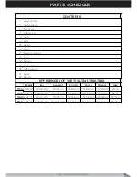
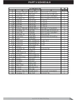
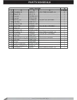
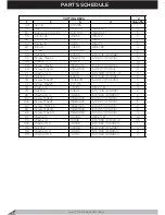
Page 39: ... T140 009 916 PA0093 01A PA0100 00A PA3836 00 PA3838 00 PC3228 00 92 797 T160 009 917 P0093 01A P0100 00 P3836 00 P3838 00 PB3228 00 92 797A T180 009 918 PA0093 01A PA0100 00A PA3836 00 PA3838 00 PA3228 00 92 797A Plate Decals CONTENTS Seat Bunker Gear shifting Lift segment DIFFERENCES OF THE T130 T140 T160 T180 Lawn tractor Cutting deck Front axle Lifting level Hub Box Hood Panel Electrical syste...

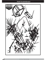
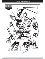
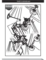
Page 40: ...Lawn Tractor Rear Discharge 40 PARTS SCHEDULE T130 T160 T140 T180 LAWN TRACTOR 1A ...

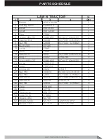
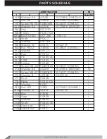
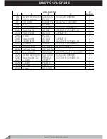
Page 41: ...her 11 40110 ISO7089 DIN125 A 8 16 Ring 7 43607 DIN6799 4 17 150B0825 ISO4017 DIN933 4 19 Lever P3182 00 1 20 Lever P3181 00 1 21 Circlip 20 43120 DIN471 2 22 Nut M10 340B10 ISO4032 DIN934 2 23 Nut M10 32810 ISO7040 DIN982 2 32 Washer 9 40108 ISO7089 DIN125 A 4 35 Washer 8 40308 DIN127 B 4 36 Nut M8 32808 ISO7040 DIN982 4 47 Cock 008 681 1 48 Tank P0778 1 49 Tank cover 008 513 1 50 hoop 10 16 676B...

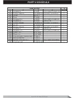
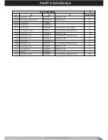
Page 42: ...r 11 40110 ISO7089 DIN125 A 2 102a Washer 10 40310 DIN127 B 2 117 Spring 008 051 1 118 Rope P0260A 00 1 120 Screw P0260 01 1 121 Nut M8 350B08 ISO4035 DIN439 2 127 Lever P0861 1 128 Segment P0774 1 129 Washer 9 40108 ISO7089 DIN125 A 6 130 Screw M8x20 150B0820 ISO4017 DIN933 3 131 Washer 8 40308 DIN127 B 3 133 Nut M8 32808 ISO7040 DIN982 3 134 Pin 6x25 5280625 ISO8752 DIN1481 2 135 Rope P0775A 00 ...

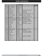
Page 43: ...3 Holder P0186 1 215 Screw M8x20 150B0820 ISO4017 DIN933 1 216 Screw M8x20 150B0820 ISO4017 DIN933 2 217 Washer 8 4 40208 ISO7093 DIN9021 4 218 Washer 8 40308 DIN127 B 3 220 Nut M8 32808 ISO7040 DIN982 3 248 Screw M6x16 2850616 ISO8677 DIN603 2 249 Washer 6 6 40106 ISO7089 DIN125 A 3 250 Washer 6 40306 DIN127 B 2 251 Nut M6 32806 ISO7040 DIN982 5 316 Bunker P3101 1 382 Grip 008 702 1 384 Spring 00...

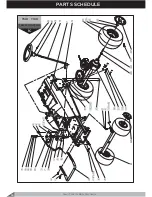
Page 44: ...T130 T160 T140 T180 LAWN TRACTOR 1B PARTS SCHEDULE Lawn Tractor Rear Discharge 44 ...

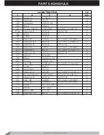
Page 45: ... 40108 ISO7089 DIN125 A 11 36 Nut M8 32808 ISO7040 DIN982 4 37 Washer 8 40308 DIN127 B 4 38 Nut M10 340B10 ISO4032 DIN934 1 39 Seal P3228C 1 40 Silencer PC3228 00 12 5 13 5 1 40a Silencer PA3228 00 17 5 1 40b Silencer PB3228 00 15 5 1 41 Screw P3228D 2 42 Washer 8 40308 DIN127 B 2 44 Tube P3640 1 46 Nut M16 1 5 074 87 1 105 Switch 019 546 00 1 105a Switch Nut 019 546 03 1 141 Pulley P0697 1 142 Wa...

Page 46: ...0310 DIN127 B 1 160 Nut M10 1 341B10 ISO8673 DIN934 1 162 Washer 019 371 2 164 Hub P0354 1 165 Pin P0585 00 1 167 Foot P0345 1 168 Holder P0666 1 171 Screw M8 25 150B0825 ISO4017 DIN933 2 172 Washer 8 4 40208 ISO7093 DIN9021 10 173 Screw M8 12 150B0812 ISO4017 DIN933 4 174 Washer 8 40308 DIN127 B 8 177 Foot P0346 1 178 Plate P0341 00 1 181 Washer P0211 1 182 Nut M12 32812 ISO7040 DIN982 1 182a Was...

Page 47: ...7 326 Splint pin 3 2 18 5003218 ISO1234 DIN94 2 327 Screw M10 30 150B1030 ISO4017 DIN933 1 328 Washer 11 40110 ISO7089 DIN125 A 2 329 Washer 10 40310 DIN127 B 1 330 Nut M10 32810 ISO7040 DIN982 1 331 Pedal P0564 00 1 332 Pedal 008 135 1 333 Bearing P0555 1 334 Insert P0743 2 335 Screw M8 22 150B0822 ISO4017 DIN933 4 336 Washer 8 40308 DIN127 B 4 337 Nut M8 32808 ISO7040 DIN982 4 338 Washer 9 40108...

Page 48: ...Spring 008 205 1 361 Draw rod P0645 00 1 363 Nut M8 32808 ISO7040 DIN982 1 374 Spacer P0437 1 375 Draw rod P0404 00 1 376 Washer 9 40108 ISO7089 DIN125 A 2 377 Nut M8 32808 ISO7040 DIN982 1 378 Spring 008 212 1 380 Splint pin 2 5 25 5002525 ISO1234 DIN94 1 381 Spring 008 226 1 383 Grip 008 695 1 397 Left protector F0003 00 1 398 Right protector F0004 1 399 Washer 17 40116 ISO7089 DIN125 A 1 LAWN T...

Page 49: ...T130 T160 LAWN TRACTOR 1C Lawn Tractor Rear Discharge 49 PARTS SCHEDULE ...

Page 50: ...T140 T180 LAWN TRACTOR 1C PARTS SCHEDULE Lawn Tractor Rear Discharge 50 ...

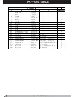
Page 51: ...0 ISO8673 DIN934 4 62a Nut M10 1 25 341C10 ISO8673 DIN934 2 63 Buffer P3791 1 64 Screw M10x1 25x40 151C1040 ISO8765 DIN960 4 65 Segment P0100 00 1 65a Segment PA0100 00A 1 66 Bush P0876 1 67 Screw M12x1 25x70 151B1270 ISO8765 DIN960 1 68 Washer 13 5 40112 ISO7089 DIN125 A 1 69 Washer 12 40312 DIN127 B 1 70 Nut M12x1 25 341B12 ISO8673 DIN934 1 71 Washer 13 40212 ISO7093 DIN9021 1 72 Washer P0101 1 ...

Page 52: ...O7089 DIN125 A 3 202a Washer 8 40308 DIN127 B 3 205 Yoke P0120 1 206 Washer 8 40308 DIN127 B 2 206a Washer 9 40108 ISO7089 DIN125 A 2 207 Nut M8 32808 ISO7040 DIN982 2 223 Wheel tyre 027 692 18 8 50 8NHS 2 223a Wheel hub 027 692A 2 224 Key B5x65 5510565 ISO773 2491 DIN6885 2 225 Splint pin 5x30 5000530 ISO1234 DIN94 2 226 Washer G 3 0 P3541A ISO7089 DIN125 A 2 227 Cover P3487 2 228 Cover P3486 2 2...

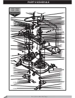
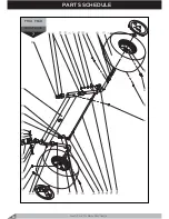
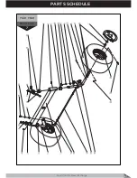
Page 53: ...T130 T160 T140 T180 LAWN TRACTOR 1D Lawn Tractor Rear Discharge 53 PARTS SCHEDULE ...

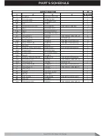
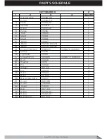
Page 54: ... 238 Nut M6 328B06 ISO10511 DIN985 4 241 Pannel P3288 1 242 Washer 8 4 40208 ISO7093 DIN9021 4 243 Screw M8x16 150B0816 ISO4017 DIN933 8 244 Washer 9 40108 ISO7089 DIN125 A 4 245 Washer 8 40308 DIN127 B 8 246 Seat switch 019 546 1 246a Switch Nut 019 546 03 1 247 Fender P3562 00 1 248 Screw M6x20 150B0620 ISO4017 DIN933 2 249 Washer 6 4 40206 ISO7093 DIN9021 4 250 Washer 6 40306 DIN127 B 2 251 Nut...

Page 55: ... DIN9021 1 292a Washer 6 40306 DIN127 B 1 293 Screw M6x16 150B0616 ISO4017 DIN933 1 294 Cover P3349 02 1 294a Screw M5x14 150B0514 ISO4017 DIN933 1 295 Washer 5 40305 DIN127 B 1 295a Washer 5 5 40205 ISO7093 DIN9021 1 299 Floor R 007 903 1 300 Floor L 007 896 1 394 Accumulator depositary F0002 1 395 Belt protector F0005 1 395b Screw ST6 3x13 C 2716313 ISO7049 DIN7981 2 396 Silencer net F0006 00 1 ...

Page 56: ...T130 T160 T140 T180 CUTTING DECK 2 PARTS SCHEDULE Lawn Tractor Rear Discharge 56 ...

Page 57: ...ade P0226 D0226 1 18 Blade P0225 D0225 1 19 Screw M10x1x25 151B1025 ISO8676 DIN961 2 20 Screw P3220 2 26 Tightener P0081 1 27 ScrewM8 35 1920835 ISO8677 DIN603 1 28 Hub P0038 1 30 Washer P0151 1 31 Pin P0048 4 32 Wheel 012 441 8 34 Pin P0039 4 36 Bush P0049 4 37 Bush 011 600 4 38 Box angle plate P0037 1 41 Cover 026 963 1 42a Cover P3600A 1 42 Cover P3600 1 44 Belt 007 441 1 45 Roller P3149 00 2 4...

Page 58: ...71 Washer 4 5 40104 ISO7089 DIN125 A 3 73 Nut M5 32805 ISO7040 DIN982 2 76 Screw M6x20 1840620 ISO4162 DIN6921 2 77 Screw M6x25 277 415 4 78 Washer 6 40306 DIN127 B 4 79 Nut M6 32806 ISO7040 DIN982 2 80 Washer 6 4 40206 ISO7093 DIN9021 2 82 Screw M8x22 150B0822 ISO4017 DIN933 6 82a Screw M8x25 150B0825 ISO4017 DIN933 1 83 Screw M10x25 150B1025 ISO4017 DIN933 2 84 Screw M8x30 150B0830 ISO4017 DIN93...

Page 59: ...A 1 100 Nut M6 32806 ISO7040 DIN982 4 102 Washer 13 5 40112 ISO7089 DIN125 A 4 103 Washer 6 40306 DIN127 B 18 104 Washer 5 5 40105 ISO7089 DIN125 A 2 105 Washer 5 40305 DIN127 B 2 107 Holder P3587A 1 108 Washer 11 40110 ISO7089 DIN125 A 3 109 Washer 10 40310 DIN127 B 2 110 Washer 4 40304 DIN127 B 3 111 Bush N0081 1 112 Washer 6 6 40106 ISO7089 DIN125 A 10 CUTTING DECK ...

Page 60: ...T130 T160 FRONT AXLE 7 PARTS SCHEDULE Lawn Tractor Rear Discharge 60 ...

Page 61: ...T140 T180 FRONT AXLE 7 Lawn Tractor Rear Discharge 61 PARTS SCHEDULE ...

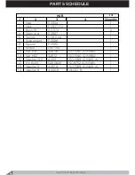
Page 62: ... 25x55 151C1055 ISO8765 DIN960 1 12 Washer 11 40110 ISO7089 DIN125 A 2 13 Nut M10 1 25 341C10 ISO8673 DIN934 1 15 Bar P0797 01 1 16 Pin P0093 10 00 1 16a Pin L P0093 20 00 1 17 Washer 11 40110 ISO7089 DIN125 A 2 18 Nut M10 1 341B10 ISO8673 DIN934 3 18a Nut M10 1 L B0001 ISO8673 DIN934 1 19 Washer 10 40310 DIN127 B 3 20 Bearing 027 685A 03 6 21 Wheel tyre 027 685 15 6 00 6NHS 2 24 Circlip 19 43119 ...

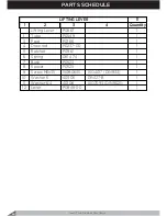
Page 63: ...T130 T160 T140 T180 LIFTING LEVER 11 Lawn Tractor Rear Discharge 63 PARTS SCHEDULE ...

Page 64: ...Lever P0861 1 1 Tube P0549 1 3 Pawl P0166 1 4 Draw rod P0237 00 1 5 Ratchet P0961 1 6 Spring 081 474 1 7 Bush P0523 1 8 Spacer P0525 1 9 Screw M6x35 150B0635 ISO4017 DIN933 1 10 Washer 6 40306 DIN127 B 1 11 Washer 6 4 40106 ISO7093 DIN9021 1 12 Lever P0848 00 1 LIFTING LEVER ...

Page 65: ...T130 T160 T140 T180 HUB 14 Lawn Tractor Rear Discharge 65 PARTS SCHEDULE ...

Page 66: ...2 2 4 Draw rod P0587 1 6 Spring 008 044 1 7 Suspension P0588 1 8 Spacer P0590 1 11 Screw 067 312 1 13 Nut M8 32808 ISO7040 DIN982 1 14 Nut M12 32812 ISO7040 DIN982 1 15 Washer 13 5 40112 ISO7089 DIN125 A 1 17 Pin 6x25 5280625 ISO8752 DIN1481 1 18 Washer 9 40108 ISO7089 DIN125 A 1 19 Washer 8 40308 DIN127 B 1 HUB ...

Page 67: ...T130 T160 T140 T180 REAR AXLE 15A Lawn Tractor Rear Discharge 67 PARTS SCHEDULE ...

Page 68: ...aft P0278 1 15 Shaft P0279 1 16 Axle P0178 00 1 80 Bearing 6204 2RS 096 472 3 81 Bearing 6004 2RS 477 942 1 86 Circlip 47 43047 DIN472 2 87 Circlip 42 43042 DIN472 1 93a Screw M6x20 150B0620 ISO4017 DIN933 6 95 Screw M8x20 150B0820 ISO4017 DIN933 3 97 Washer 6 6 40106 ISO7089 DIN125 A 6 97a Washer 6 40306 DIN127 B 6 98 Washer 9 40108 ISO7089 DIN125 A 3 98a Washer 8 40308 DIN127 B 3 REAR AXLE ...

Page 69: ...T130 T160 T140 T180 REAR AXLE 15B Lawn Tractor Rear Discharge 69 PARTS SCHEDULE ...

Page 70: ... 016 876 1 29 Washer P0267 2 2 31 Box angle plate P0844 1 31a Pin N0701 1 32 Coupling P0893 1 33 Fork P0187 1 34 Bar P0882 1 35 Cover N0702 1 35a Washer6 40306 DIN127 B 2 35b Screw M6 12 150B0612 ISO4017 DIN933 2 36 Ball 098 351 ISO3290 DIN5401 1 37 Spring 011 992 1 38a Washer6 5 402B06 DIN6916 1 38b Washer6 40306 DIN127 B 1 38c Screw M6 12 150B0612 ISO4017 DIN933 1 39 Screw M6x16 283A0616 ISO7435...

Page 71: ...er 019 364B 2 53b Washer 019 364C 1 53c Washer 019 371B 1 54 Tichtener P0646 00 1 55 Pulley P0356 1 55a Bearing 6002 2RS Q0001 10 30 9 2 55b Bush 12 17 12 Q0002 12 17 12 2 57 Holder P0115 1 58 Roller A8x32 5210832 ISO2338 DIN7 2 60 Lever P0353 1 61 Plate P0325 1 62 Pin P0397 1 68 Screw M8x25 1200825 DIN939 1 69 Screw M8x20 150B0820 ISO4017 DIN933 1 69a Nut M8 340B08 ISO4032 DIN934 3 70 Nut M8 3320...

Page 72: ...ing 6005 2RS 620 012 25 47 12 2 84 Circlip 10 43110 DIN471 1 84a Nut M10 38010 ISO7035 DIN935 1 84b Split pin 2 5x25 5002525 ISO1234 DIN94 1 85 Circlip 25 43125 DIN471 2 86 Circlip 47 43047 DIN472 1 89 Pin 4x30 5280430 ISO8752 DIN1481 1 92 Screw M6x25 150B0625 ISO4017 DIN933 4 93 Screw M6x25 150B0625 ISO4017 DIN933 3 93a Screw M6x20 150B0620 ISO4017 DIN933 4 94 Screw M6x25 150B0625 ISO4017 DIN933 ...

Page 73: ...T130 T160 T140 T180 HOOD 24 Lawn Tractor Rear Discharge 73 PARTS SCHEDULE ...

Page 74: ...C 1 3a Headlamp seat R 647 081C 1 3b Headlamp cover R 013 373C 1 4 Vent upside P3562A 02 1 5 Sponge N2003 1 6 Screw ST8 19 2710819 ISO7049 DIN7981 8 7 Link L P3565A 06 1 8 Link R P3565A 07 1 9 Bumper P3565A 05 1 10 Screw ST6 3 22 2716322 ISO7049 DIN7981 9 11 Screw ST6 3 19 2716319 ISO7049 DIN7981 4 13 Vent front L P3563A 03 1 14 Vent front R P3564A 04 1 15 Screw ST2 9 9 5 2712995 ISO7049 DIN7981 6...

Page 75: ...T130 T160 T140 T180 PANEL 25 Lawn Tractor Rear Discharge 75 PARTS SCHEDULE ...

Page 76: ... ISO4032 DIN934 8 17 Plugboard 007 770 1 18 Decal dashboard P3349 01K 1 19 Washer 4 3 40104 ISO7089 DIN125 A 2 20 Washer 4 40304 DIN127 B 2 21 Screw M4 10 2140410 ISO7045 DIN7985 2 22 Screw M6 14 150B0614 ISO4017 DIN933 1 23 Washer 6 40306 DIN127 B 3 24 Washer 6 6 40106 ISO7089 DIN125 A 2 25 Foot P3206 1 26 Screw M6 14 150B0614 ISO4017 DIN933 2 28 Washer 6 5 402B06 DIN6916 1 29 Lever P3142A 00 1 3...

Page 77: ...T130 T160 T140 T180 ELECTRICAL SYSTEM 27 Lawn Tractor Rear Discharge 77 PARTS SCHEDULE ...

Page 78: ...T130 T160 T140 T180 ELECTRICAL SYSTEM 27a PARTS SCHEDULE Lawn Tractor Rear Discharge 78 ...

Page 79: ...306 DIN127 B 2 19 Nut M6 32806 ISO7040 DIN982 2 21 Switch 019 546 3 26 Seat Switch 019 546 1 28 Rubber inlet 052 593 3 31 Composition 007 770 1 41 Headlamp cover L 013 373B 1 41a Headlamp cover R 013 373C 1 42 Headlamp seat L 647 081B 1 42a Headlamp seat R 647 081C 1 43 Lamp 310 181A 2 43a Lamp socket 310 182 2 48 Nut M8 340B08 ISO4032 DIN934 4 49 Washer 9 40108 ISO7089 DIN125 A 4 50 Washer 8 4030...

Page 80: ...T130 T160 T140 T180 SEAT 32 PARTS SCHEDULE Lawn Tractor Rear Discharge 80 ...

Page 81: ... M8x20 150B0820 ISO4017 DIN933 2 6 Nut M8 32808 ISO7040 DIN982 2 7 Washer 9 40108 ISO7089 DIN125 A 4 8 Washer 5 3 40205 ISO7093 DIN9021 2 9 Washer 5 40305 DIN127 B 2 10 Nut M5 32805 ISO7040 DIN982 2 11 Washer 8 4 40208 ISO7093 DIN9021 4 12 Screw M8x20 150B0820 ISO4017 DIN933 4 14 Screw M5x16 2540516 ISO7046 DIN965 2 15 Seat Holder 019 532 1 16 Band 019 532B 1 SEAT ...

Page 82: ...T130 T160 T140 T180 BUNKER 34 PARTS SCHEDULE Lawn Tractor Rear Discharge 82 ...

Page 83: ...ter N3401 1 12a Screw M5x30 150B0530 ISO4017 DIN933 5 13 Washer 5 5 40105 ISO7089 DIN125 A 7 15 Nut M5 32805 ISO7040 DIN982 10 16 Screw M5x30 150B0530 ISO4017 DIN933 2 16a Screw M5x25 150B0525 ISO4017 DIN933 3 17 Belt 015 356 08 2 18 Washer 5 3 40205 ISO7093 DIN9021 5 18a Washer 5 3 40205 ISO7093 DIN9021 4 19a Screw M5x20 150B0520 ISO4017 DIN933 2 20 Screw M6 25 150B0625 ISO4017 DIN933 1 21 Nut M6...

Page 84: ...T130 T160 T140 T180 GEAR SHIFTING 35 PARTS SCHEDULE Lawn Tractor Rear Discharge 84 ...

Page 85: ...1 2 3 4 Quantity Gear shifting P0864 00 1 1 Tube P0849 1 2 Segment P0855 1 4 Bush P0523 1 5 Bush P0524 1 10 Insert P0843 1 13 Ring P0522 1 14 Roller 4x14B 5220414 ISO2338 DIN7 1 15 Washer 6 6 40106 ISO7089 DIN125 A 2 16 Spring 645 455 1 GEAR SHIFTING ...

Page 86: ...T130 T160 T140 T180 SEGMENT 36 PARTS SCHEDULE Lawn Tractor Rear Discharge 86 ...

Page 87: ...Lawn Tractor Rear Discharge 87 PARTS SCHEDULE 36 1 2 3 4 Quantity Lift segment P0774 2 1 Lift segment P0357A 00 2 3 Rope P0775A 00 2 SEGMENT ...

Page 88: ...T130 T160 T140 T180 PLATE 37 PARTS SCHEDULE Lawn Tractor Rear Discharge 88 ...

Page 89: ...M10x25 150B1025 ISO4017 DIN933 2 7 Plate GC102 90 00 1 8 Screw M6x14 150B0614 ISO4017 DIN933 2 9 Washer 6 40306 DIN127 B 2 10 Washer 6 4 40206 ISO7093 DIN9021 2 11 Washer 10 5 40210 ISO7093 DIN9021 2 12 Washer 10 40310 DIN127 B 2 13 Nut M10 32810 ISO7040 DIN982 2 14 Right hook P0324B 00 1 15 Left hook P0324A 00 1 16 Switch 019 546 1 19 Washer GC102 102 2 21 Draw Frame N2002 1 22 Switch Nut 019 546...

Page 90: ...T130 T160 T140 T180 DECALS 38 PARTS SCHEDULE Lawn Tractor Rear Discharge 90 ...

Page 91: ...9 01D 1 4 Decal Danger of cutting P3349 01F 2 5 Decal Danger of hot P3349 01M 1 6 Decal Blade engagement P3349 01H 1 7 Decal Light switch P3349 01P 1 8 Decal Key ignition switch P3349 01E 1 9 Decal Gas control lever P3349 01G 1 10 Decal Parking brake button P3349 01C 1 11 Decal Lift lever position P3349 01B 1 12 Decal Shift lever position P3349 01A 1 13 Decal Serial number 1 DECALS ...

Page 92: ...5 34 18 32810 7 22 40108 27 49 40205 34 18a 32810 37 13 40108 32 7 40205 1B 17 32810 1A 23 40108 36 6 40205 1D 295a 32810 1A 101 40108 15A 98 40206 2 80 32810 1B 330 40108 1A 32 40206 2 98 32812 14 14 40108 1A 129 40206 37 10 32812 1B 182 40108 1A 139 40206 1D 232 40206 1D 236 40308 14 19 43120 1A 21 40206 1D 249 40308 24 6 43125 15B 85 40206 1D 292 40308 27 50 43607 1A 16 40208 2 93a 40308 15A 98...

Page 93: ...008 135 1B 332 019 364C 15B 53b 150B0514 1D 294a 008 142 1B 144 019 371 1B 162 150B0516 25 7 008 156 1D 280 019 371B 15B 53c 150B0520 34 19a 008 170 1D 279 019 500 32 150B0525 34 16 008 184 1D 278 019 500 1D 271 150B0525 34 16a 008 191 1A 384 019 532 32 15 150B0525 1B 16 008 205 1B 360 019 532A 32 1 150B0530 34 12a 008 212 1B 378 019 532B 32 16 150B0612 15B 35b 008 226 1B 381 019 546 27 21 150B061...

Page 94: ...7 2 38 151C1055 7 11 900 001 7 27 P0038 2 28 214A0518 2 69 900 001 1C 230 P0039 2 34 277 415 2 77 92 792A 1A 52a P0046 2 12 280 145 7 4 92 796 1A 51 P0048 2 31 280 146 7 26 92 797 1A 52 P0049 2 36 283A0616 15B 39 92 813 1D 285 P0081 2 26 P0087 2 16 P0260A 00 1A 118 P0560 00 1B 339 P0093 01A 1C 59 P0266 15A 10 P0564 00 1B 331 P0093 10 00 7 16 P0267 15B 29 P0585 00 1B 165 P0093 10 00 1C 60 P0278 15A...

Page 95: ...0895 15B 1 P3349 01E 38 8 P3820 00 7 P0905 7 10 P3349 01F 38 4 P3820 00 1C 25 P0907 00 25 8 P3349 01G 38 9 P3836 00 7 5 P0923 34 5 P3349 01H 38 6 P3838 00 7 9 P0935 34 10 P3349 01K 25 18 PA0093 01A 1C 59a P0961 11 5 P3349 01K 38 1 PA0100 00 1C 65a P3101 34 P3349 01M 38 5 PA3228 00 1B 40a P3101 1A 316 P3349 01P 38 7 PA3820 00 7 P3103 00 34 7 P3349 02 1D 294 PA3820 00 1C 25a P3104 34 3 P3356A 00 25 ...

Page 96: ...and Gizmows Ltd Postal address PO Box 592 Kerikeri 0245 New Zealand Warehouse Offices 7 9 General Gates Avenue Kerikeri 0230 New Zealand Phone 64 Ø9 401 6360 Fax 64 Ø9 401 6350 Email info MGG co nz Website www MGG co nz ...

Reviews: