Blaze EMS-2 Operating Manual
Page 58
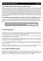
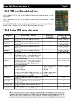
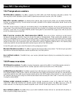
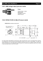
10.7 Fuel level senders
The EMS-2 permits the connection of standard automotive fuel level senders. These senders can be obtained at
automotive spares outlets at reasonable cost. When you choose a float level sender, ensure that you select a model that
is sturdy and promises reliable and long lifetime. In particular, select a model that does not have any metal parts that can
rust. The EMS-2 can interface to a large variety of these fuel level senders. It does not matter if the sender resistance
increases or decreases with the fuel level as long as it changes. The calibration procedure outlined in the “Fuel Level
Setup” section describes in great detail the procedure to follow.
In essence, the calibration procedure will measure the resistance of the fuel level sender at various fuel levels and then
work out the readings in between those known settings. Typical fuel level senders that can be used with the EMS-2 have
resistance ranges in the region of 100 ohms to 500 ohms. Connect the flange of the sender to the negative supply
(ground). You can connect capacitive senders as well. These generally come in two types: The first emulates a normal
resistive probe and is simple to connect and use as a result. The second type has a voltage level output. These can be
used if the voltage can be set to a range of about 0-5V. Higher voltage levels will result in the instrument assuming a
problem.
We recommend using VDO float based fuel level senders. Capacitive types can be used provided they have a voltage
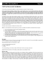
output not exceeding 5V. The analog inputs have an internal 1K5 resistor pull-up to +5V. Please note that capacitive
senders may exhibit large errors as they are very sensitive to the composition of the fuel used. We do not recommend
using capacitive senders with automotive fuels for this reason.
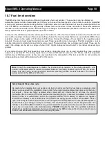
Safety Hazard! Please take note:
Be careful when installing fuel level senders into fuel tanks. Ensure that the fuel tank is completely empty
when you proceed with the installation. Ensure that the fuel tank is well ventilated and does not contain any
fuel vapors – these are highly explosive when mixed with air. Ensure that at all times the ground
connection (the connection of the fuel level sender mounting flange) is securely connected to the aircraft
frame (in case of a metal frame) and to the negative terminal of the battery. In addition the negative
terminal of the battery must at all times be connected to the supply ground terminal of the EMS-2. Please
note – this wiring is critical and must never break in flight. It would be possible to create electrical sparks in
the fuel tank if your wiring is faulty or incorrect. The consequences of this can be imagined. This has
nothing to do with the EMS-2 itself but is a general hazard for any automotive fuel level sender installation.
If you have no experience with electrical wiring,
PLEASE
delegate the task to a qualified automobile
electrician or electronics technician. If you need to remove the EMS-2, please first disconnect and secure
the fuel level sender wire before disconnecting anything else.
Note:
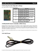
It might be advantageous to disable the internal pull up resistor via the analog dipswitch and
provide a calculated external resistor connected between the analog channel input and the +5V sensor
power. This can lead to an increased ADC resolution providing a better fuel tank indication. The internal
pull up resistor in the EMS-2 is 1k5 ohms.


