


Blaze EMS-2 Operating Manual
Page 61
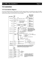
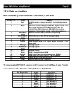
10.14 Cable connections
Main connector (D15HD connector: Unit Female, Cable Male)
Thermocouple (EGT/CHT) connector (D9 connector: Unit Male, Cable Female)
In case of MGL Avionics
K-Type
probes
+ = Yellow probe lead, - = Red probe lead
D15HD Pin
Color
Function
1
Red
8-30Vdc power via power switch / circuit breaker and
fuse.
2
Black
Ground. Connect the ground to the engine block, and
the engine block to the battery negative. Do not
connect the EMS-2 ground directly to the battery
negative. This must be routed via the engine block.
3
White/Blue
Stripe
RS232 Transmit data (Firmware upgrading)
4
White/Black
Stripe
RS232 Receive data (Firmware upgrading)
5
Green
Analog Input 2
6
Yellow
RPM 2 (Rotor RPM / TTL signal sensor sources) / Fuel
flow Input
7
Orange
Analog Input 1
9
Red/White
Stripe
Analog Input 4
10
Grey
Analog Input 3
11
Blue
RPM 1 Input (Engine RPM)
12
Purple
CAN Low (Used for optional external RDAC)
13
Pink
CAN High (Used for optional external RDAC)
14
Brown
+5Vdc Power out Sensor power
15
White
Alarm Output (Open collector)
D9 Female Pin
Color
Function
5
Blue
TC Channel 1 +
4
Orange
TC Channel 2 +
3
Green
TC Channel 3 +
2
Purple
TC Channel 4 +
9
Red
TC Channel 1 -
8
Brown
TC Channel 2 -
7
Yellow
TC Channel 3 -
6
White
TC Channel 4 -