background image

Ergonomical considerations

Enigma contains a very advanced LCD display that is able to perform well in direct sunlight 
conditions. In order to achieve this and further ensure low power consumption, the display 
contains a “light director”. This focuses the major part of available light towards the viewer, 
creating a brighter image but also reducing the effect of ambient light falling at an angle 
onto the display surface.
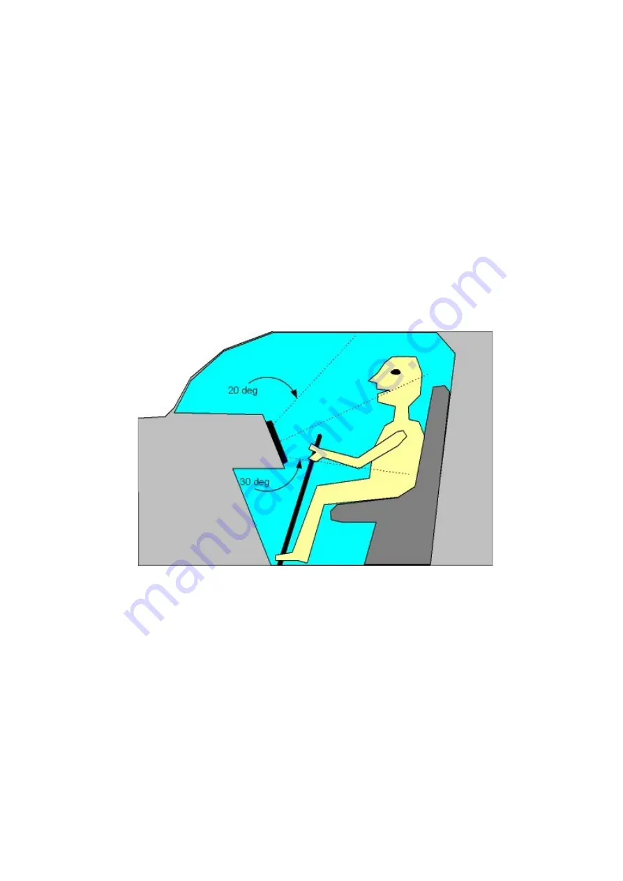
In order to take optimum advantage of this, the panel should be installed such that the 
pilots eye will look onto the panel in a vertical -30 to +20 degree angle maximum. The 
negative angle would be applicable for a steeply sloped panel where you would be looking 
onto the panel from below.
This can be achieved in two ways: Mount the instrument as high as possible onto the 
panel. This also aids the pilot as the image is closer to the windscreen avoiding eye fatigue 
while constantly changing view from the panel to outside the aircraft.
If this is not possible or can only be done in a limited way, consider tilting the instrument up 
slightly in order to aim the picture towards the pilot.

Idealized view of a sloped panel to optimize viewing quality. This image overdoes this 
somewhat, in practice the panel does not have to be angled this much and if it is possible 
to install the instrument relatively high on the panel, it is not normally required to mount the 
instrument angled.
Preferred horizontal viewing angles are within left 50 degrees to right 50 degrees. If a 
single instrument is to be shared between two pilots seated side by side, consider 
installation of the instrument towards the center of the panel or alternatively angle it 
towards the disadvantaged side somewhat. The panel can be read as angles greater than 
+/-50 degrees but with reduced brightness.

Summary of Contents for Stratomaster Enigma

Page 1: ...Stratomaster Enigma Preliminary installation documentation ...

Page 2: ...another for the backup battery In flight both switches would be on allowing the charging of the backup battery Preflight check would involve switching main power on then battery power on Check of battery power would involve switching main power off and verifying that Enigma continues to operate Voltage on the backup battery should be measured by means of the backup voltage readouts which can be pl...

Page 3: ...ferrite beads on ALL wires leaving the instrument Four ferrite beads are included with each instrument as standard These ferrite beads are vital to eliminate any RF interfering signals that may cause radio interference particularly on VHF radios Beads may or may not be required this will depend highly on installation and routing of wiring in the aircraft As a rule follow these guidelines Antenna c...

Page 4: ...nt on the contents of the display and may sound like an angry grrrrrr If you have radio noise change the screens to see if the noise pattern changes as well If it does start identifying which cables are used to transmit the noise to your radio Enigma itself does not transmit a significant signal due to strict EMI design techniques however small signals may readily leak and use any attached wires a...

Page 5: ...AOA port types Photo of an experimental single port AOA probe mounted next to the pitot tube on the wing strut of our Jora aircraft This probe made from wood works very well indeed ...

Page 6: ... panel This also aids the pilot as the image is closer to the windscreen avoiding eye fatigue while constantly changing view from the panel to outside the aircraft If this is not possible or can only be done in a limited way consider tilting the instrument up slightly in order to aim the picture towards the pilot Idealized view of a sloped panel to optimize viewing quality This image overdoes this...

Page 7: ...ion suitable for connection to a mode C transponder Connections using the standard code identifiers are shown here If your transponder does not support signals D4 and D2 leave them unconnected At least one of the ground wires should be connected to the corresponding ground terminal of your transponder ...

Page 8: ...Transponder connections for popular models ...

Page 9: ...Transponder interface wiring for Microair T2000 ignore pin numbers on DB15 connector Also line Encoder power is not used with Enigma ...

Reviews: