background image

25


24.11.14 / V 01.0-E 

Operation 

18. Operation 
 
Vor dem Arbeitsbeginn 


Before starting the work  

 
1.  Check the material to be processed.  


Can the material be milled  


Check the drawing (bevel angle, size, processing )    


2. Pay attention to a sufficient fixation of the material 

For safety reasons, 
To reduce vibration (improves the service life of the indexable inserts) 
 

3. Prepare the machine 


Select the required milling head off (bevel angle) 


Mount it with the correct inserts (depending on material) 


Adjust the first cutting height 


4. 

Pay attention to a proper working environment 


Ensure that the work area is free of tripping hazards 


Ensure that nobody is in the area of the chips flying  


Ensure that no flammable objects are in the worksplace  


5. 

Wear your personal protective equipment  


Glasses, work gloves, hearing protection, safety shoes and  


a  leather apron 


Mit der HBM R3 arbeiten:    

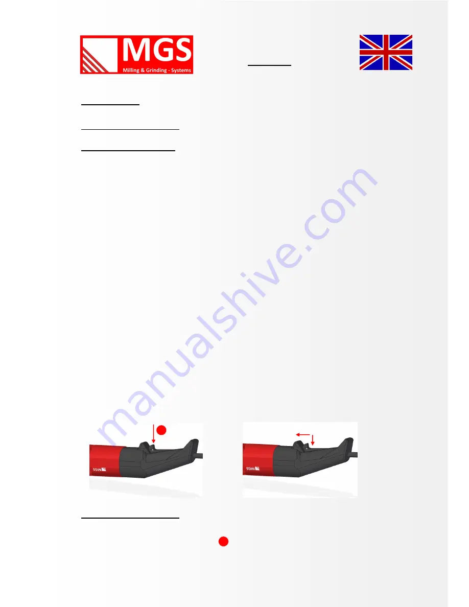
To exclude accidental starting edge milling machine HBM R3, the starter of the machine 

is equipped with a locking startup. 

Summary of Contents for HBM R3

Page 1: ...24 11 2014 V 01 0 E 1 Reference Hand guided Milling Machine Short Term HBM R3 Documentation starting with A04 003 0001 Operating Manual Hand guided Milling Machine HBM R3 ...

Page 2: ...shausen Phone 49 0 6873 6690021 Fax 49 0 6873 6690020 Mail info mgs maschinen de Mobile 49 0 160 7742434 Internet www mgs maschinen de Managing Director Guido Schnur Entry in Commercial Register HRB 101 269 Amtsgericht Saarbrücken VAT Identification Number DE 291 965 479 Relevant chamber Arbeitskammer des Saarlandes ...

Page 3: ...intended use 8 Technical data 9 Operating 10 Vibration measurement 13 On Time 14 Setting and adjustment of bevel size 15 Standard milling machine 16 Indexable cutting inserts for bevels 19 Indexable cutting inserts for radius 20 Setting and adjustment of radius 21 Operating of the machine 25 Schedule of maintenance 27 Service 28 Parts list gear 32 Parts list motor 34 Warranty conditions 37 EC Decl...

Page 4: ...ng of the machine will prevent accidents reduce costs and im prove the quality of your work piece Before being packed and delivered to you the machine has been closely tested and checked In order to be able to help you as fast and efficient as possible we would ask you to kindly indicate the MGS machine identification number in any case This number is to be found in the supplied operating manual a...

Page 5: ...y time The steps given below must be taken by the operator in any case to avoid improper handling of the machine or to prevent accidents Installation The machine must only be connected to the voltage indicated on the machine s label Danger to life from electrocution Before starting maintenance work disconnect the machine from the power plug The machine has to be unplugged and volt free Before each...

Page 6: ...machine at high speed Use impact protection Risk of injury from ejected indexable inserts Use only original MGS inserts and clamping screws Tighten the clamp screws with 3 4 Nm torque Health risk in case of inhaling cutting oil Sufficient venting is essential for working with cutting oil Do not inhale arising vapors Improper use can damage equipment and property Risk of machine being damaged or de...

Page 7: ...ockwise in case of working on bore holes or channels c Bore Diameter or Inner Radius In order to avoid a hooking of the cutting plates on starting the beveling of bore holes the bore hole should always be at least 1 5 fold of the guide bearing In case of guide bearing of 45 milling machine the bore diameter is thus 24 8 mm x 1 5 37 2 mm Considering sufficient inner radius for beveling of inner rad...

Page 8: ...13 locking button Intended use The hand guided edge milling machine HBM R3 is an electrically powered machine for the working of work pieces made of Steel cast steel fine grained steel stainless steel aluminium aluminium alloys brass and plastics The machine is designed for industrial use in industry and small trade for creating visible edges in plant tool and mechanical engineering for edge round...

Page 9: ...0 W idle speed 2000 6500 rpm approximate weight 3 5 kg bevel width material dependent aluminium 1 4 mm steel 1 4 mm stainless steel 1 3 mm minimum thickness of work piece 3 mm smallest contour radius at 45 18 5 mm smallest bore diameter at 45 37 2 mm edge radius 3 mm Subject to technical modifications and or amendments by the manufacturer ...

Page 10: ...utting tool Remove the clamping screw on the side of the housing with the clamping using the hexagon wrench SW 3 Remove the holder complete with the guiding plate downwards To block the drive shaft use the special wrench SW 17 the hook wrench 45 50 is used for loosening the milling head For all maintenance work the machine must be disconnected from the power supply system ...

Page 11: ...cutting tool Do not use the lock button for changing the milling head Put the machine on a solid base and set the hook wrench Remove the milling head counter clock wise and unscrew it from the spindle In reverse sequence a new milling head can be mounted ...

Page 12: ...machine on the upper surface and turn the guiding plate downwards as much as necessary to get the cutting inserts totally free so that you can turn them easily or exchange them Always use a Torx T15 We recommend to change defective plates or insert screws immediately To avoid a turning away of the milling tool lock the drive shaft with the lock button For all maintenance work the machine must be d...

Page 13: ...g protection Note The measurements were performed on a technically comparable machine Total value of vibration Vector sum of three directions Unit Value DIN 6075 Vibration emission value ah m s 4 uncertainty K for vibration emission value m s 1 5 Advice The above mentioned measured values depend on material and application and can therefore be exceeded In case bevels wider than admissible are work...

Page 14: ...igh load due to broad bevels hard ma terial or blunt cutting inserts this cooling is no longer sufficient and there is the risk that the isolation of the armature winding is damaged which might lead to short circuit Thus take care that the bevel adjustment is not too high In case of large bevels it is better to work a bevel in several strokes This also involves that there is less vibration leading...

Page 15: ...e bell to the desired scale level Then close the clamp and the height adjustment is complete On the left side of the HBM R3 you see a smaller and a larger circle They symbolize the different distance guiding bearings The marking smaller circle is used for the distance guiding bearing H3 R3 3 Ø 24 8 mm For using the distance guiding bearing Ø 32 8mm H3 R3 4 position the rim of the guiding bell to t...

Page 16: ...ng scale for the bevel dimension bevel width The Bevel width can be adjusted by turning the guiding bell After adjusting customize a sample piece and check the dimensions Due to manufacturing tolerances a readjustment may be necessary bevel width at angle bevel height 45 1 1 4 2 2 8 3 4 2 all specifications in mm ...

Page 17: ...ve H R3 R3 2 Ø32 8 1 0101 313 142 7 Fitting bolt M5 6x20 1 0101 313 143 8 Locking ring 472 19x1 1 0101 313 139 9 Bearing 626 2ZR Ø 19 0 2 0101 313 140 10 Sleeve H R3 R3 1 Ø24 8 1 0101 313 141 11 Fitting bolt M5 6x20 1 0101 313 143 The positions 2 4 and 8 are in packaging unit of 10 pieces delivered Milling head units are always delivered without indexable inserts Standard milling tool Milling head...

Page 18: ... R3 2 Guide sleeve unit completely mounted Description Short description Number Order No Guide sleeve R3 1 Ø 24 8mm 1 0101 313 147 Standard milling head Guide sleeve unit completely mounted Description Short description Number Order No Guide sleeve R3 2 Ø 32 8mm 1 0101 313 148 ...

Page 19: ...ngs for indexable inserts Other coatings on request Description Coating Colour Short description Order No WP 4 X0 Uncoated Light gray X 0 0101 213 17 WP 4 X1 ExTin Gold X 1 0101 213 18 Material Coating Colour Description Alu copper brass Uncoated Light gray X 0 Steel bis 400 N mm ExTin Gold X 1 Steel bis 600 N mm ExTin Gold X 1 Stainless steel ExTin Gold X 1 Cutting insert ...

Page 20: ... the HBM R3 following inserts are used For milling of radius WP 4 6R3 Radius 3mm WP 4 6R3 Other coatings on request Description Coating Colour Short descripti Order No WP 4 6R3 X0 Uncoated Light gray X 0 0101 213 19 WP 4 6R3 X1 ExTin Gold X 1 0101 213 20 ...

Page 21: ...ter may result in a 7 deviation of the upper and end faces of the workpiece Depending on how the plate is milled there can always be different cutting results So if you want to mill a radius R3 mount the sleeve H3 R3 3 4 and then adjust the height of the guide plate Customize a test piece and corret the height adjustment The guide plate always closes with the end of the radii plate Radius ...

Page 22: ...ows Milling smaller bore holes or smaller inner con tours use the small distance guiding bearing H3 R3 1 Ø 24 8mm Mount the radius inserts WP 4 6 R3 in to the upper bore hole By turning of the carbide insert 2 cutting edges can be used processing smaller bore holes Employed cutting edges are 1 an 2 1 2 ...

Page 23: ...lease mount the larger distance guiding bearing H3 R3 1 Ø 24 8mm The carbide insert stays mounted in the upper position By turning the middle cutting edges 3 and 4 can be used By mounting the carbide inserts in to the lower bore hole position the cutting edges 5 and 6 can be employed 3 4 5 6 ...

Page 24: ... low is milled your material on the surface Is the guide plate set too high the radius is not completely formed If the setting is right the radius is correct Important Always pay attention to the correct guide sleeve Only in this way it is ensured that the radius can also be laterally milled properly Radius ...

Page 25: ... milling head off bevel angle Mount it with the correct inserts depending on material Adjust the first cutting height 4 Pay attention to a proper working environment Ensure that the work area is free of tripping hazards Ensure that nobody is in the area of the chips flying Ensure that no flammable objects are in the worksplace 5 Wear your personal protective equipment Glasses work gloves hearing p...

Page 26: ... release the lock Once the motor is switched off wait for the standstill before placing down the machine Check the bevel size and if necessary correct the machine setting Recommendation In order you get to know your edge milling machine start with a small chamfer width You will fast learn the easy handling of the machine and than to edit larger chamfers Please note that the larger the bevel is set...

Page 27: ...enance work the machine must be disconnected from the power supply system Part to be serviced Type of maintenance work Materials required Order No Ventilation slots Clean as required Mitre gear Replace as required Lubricating grease 0101 313 100 Height adjuster thread Clean and replace as necessary Lubricating grease 0101 313 100 Guide bearing Replace as necessary See page Indexable cutting Rotate...

Page 28: ...iciently Servicing 2 Attention To perform a grease change you have to open the machine Do not do it during the warranty period because otherwise your lose the warranty Remove the clamping screw on the side of the housing with the clamping using the hexagon wrench SW 3 Remove the holder complete with the guiding plate downwards See page 11 inlet air exhaust air ...

Page 29: ...ricate the height adjustment disassemble the guide plate and screw the lead bell to the top Servicing 4 Changing the distance guiding bearing Unscrew the fitting screw using the hexagon wrench SW 3 Take off the spring ring using spring ring pliers Remove the bearing out of the guiding sleeve and replace it While dismantling and mounting always pay attention to the distance washers Servicing 5 Repl...

Page 30: ...es are on the left and right side under the handle scales To open this loosen the 4 screws on the handle Then lift up carefully the left handle scales Always make sure that only one handle scales is removed Then you will see the following parts Connection cable with clamp Coal with connection cable Coil spring Rotor ...

Page 31: ...ing Put the power cord firmly back on Close the machine with the molded handle and then open the right side of the machine Replace the carbon brush on the right side using the same technique Close the machine with the molded handle and bolt down the four Phillips Screws Your machine is now ready for use After a replacement of the carbon brush the brush fire is initially slightly larger but after s...

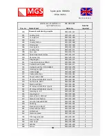
Page 32: ...letely 0101 313 202 1 10 Countersunk screw M5x12 0101 313 164 4 11 Guide plate HBM R3 0101 313 206 1 12 Wing screw 0101 313 151 1 13 Sleeve for wing screw 0101 313 152 1 14 Threaded housing M 6 M8x6 0101 313 93 1 15 Housing with clamping HBM R3 0101 313 207 1 16 Cylinder head screw M5 x20 0101 313 58 1 17 Guiding bell HBM R3 0101 313 208 1 18 Threaded housing M 5 M7x7 5 0101 313 162 4 ...

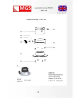
Page 33: ...33 24 11 14 V 01 0 E exploded drawing HBM R3 Gear unit exploded drawing Gear unit ...

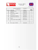
Page 34: ... 0101 313 178 2 115 Handel grip right 0101 313 179 1 116 Cable bridge 0101 313 180 1 117 Cable protection 0101 313 181 1 118 Power cable 230V 0101 313 182 1 119 PT Screw WN 1442 B 3 5x 12 0101 313 183 2 120 Switch look 230 V 0101 313 184 1 121 Electronic 230 V 0101 313 185 1 122 PT Screw WN 1442 B 3 5x 12 0101 313 183 2 123 PT Screw WN 1442 B 3 5x 25 0101 313 186 2 124 Handel grip left 0101 313 18...

Page 35: ...139 Hand spacer in front 0101 313 85 1 140 Rubber grip 0101 313 76 1 141 Countersunk screw M8x30 0101 313 86 2 142 Handle side L R 0101 313 129 2 143 Countersunk screw M 5x25 0101 313 87 2 144 Cylinder head screw M 10x30 0101 313 212 2 145 Washer 0101 313 211 2 146 Handle connection middle HBM R3 0101 313 204 1 148 Standard gear unit HBM R3 0101 313 205 1 ...

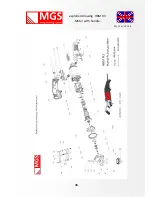
Page 36: ...36 24 11 14 V 01 0 E exploded drawing HBM R3 Motor with handle ...

Page 37: ...tions or repair work carried out or parts foreign and non original accessories or supplies were installed MGS does in these cases and for the consequences arising from any warranty Warranty claims will only be accepted if the unit is unopened and undismantled returned to MGS The granting of a warranty will not extend the warranty period nor do they initiate a new warranty period in the running Of ...

Page 38: ...nt and of the Council of 17 May 2006 on machinery and amending Directive 95 16 EC Revised 2006 42 EC Directive 2006 95 EC of the European Parliament and of the Council of 12 December 2006 on the ap proximation of the laws of Member States relating to electrical equipment designed for use within certain voltage limits 2006 95 EC Directive 2004 108 EC of the European Parliament and of the Council of...

Reviews: