––– STEP 5 –––
INSTALLING AND CONNECTING
OTHER DEVICES
As well as the gearmotor with control unit (WT1SC) the “WT” system also
comprises other optional devices and accessories which can be installed
at any time on the automation. The devices required to set up a standard
automation are described here in Step 5; the others (back-up battery PR2
and PF photovoltaic power supply) are described in the chapter “Further
details”.
5.1 - CONNECTING THE GEARMOTOR WT1SK
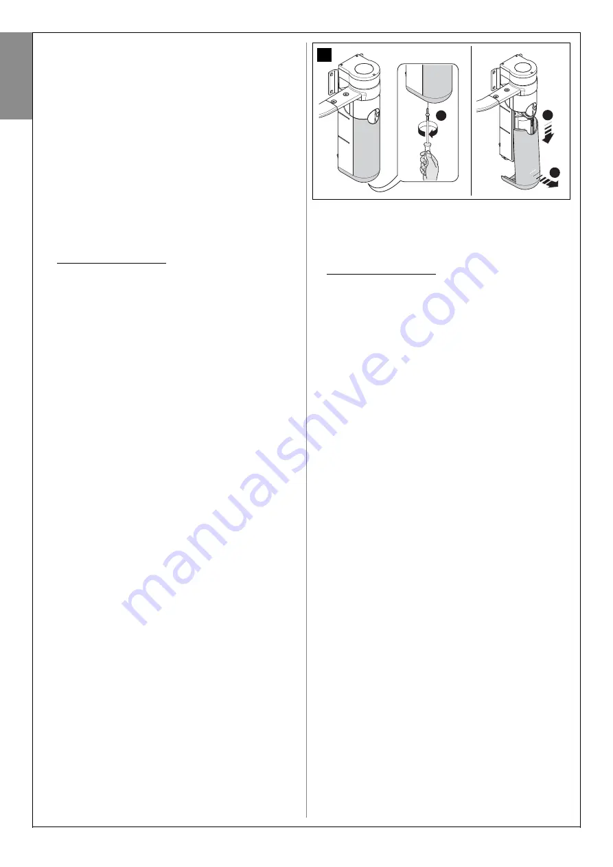
01.
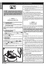
Remove the lower cover of the gearmotor without control unit, as
shown in
fig. 22
;
02.
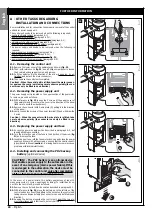
(for the next phases, refer to
fig. 23
) Use a screwdriver to loosen the
4 screws of the ducting support and remove (
Caution!
- take care to
conserve the 2 spacers).
03.
Loosen the cable clamp and pass the connection cable under-
neath; connect the 3 electric wires to the terminal board taking care
to observe the symbols on the label; then tighten down the cable
clamp screws.
04.
Adjusting the gearmotor feet.
Before proceeding, adjust the height
of the 2 feet at the rear of the gearmotor. These should touch the sur-
face of the post to increase stability of the gearmotor. These should
touch the surface of the post to increase stability of the gearmotor.
Then use a hex wrench inside the gearmotor, to make adjustments as
shown in phase 7 of
fig. 23
.
Caution!
– Never tighten the feet
more than necessary: they just need to touch the surface.
05.
Lastly, cut the edge of the cable ducting support; refit the 2 spacers,
refit the ducting support and close the gearmotor.
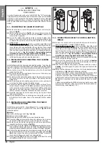
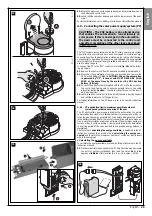
5.2 - INSTALLING AND CONNECTING THE FLASHING
LIGHT FL100
Install the flashing light in the previously selected position. To perform the
work, refer to fig. 24. In this figure fixture on a vertical wall is marked with the
letter “A”; while fixture on a horizontal surface is marked with the letter “B”.
01.
Loosen the screw of the transparent cover, turn it to the right and
extract from the base.
02.
Pull out the lamp support and loosen the screws on the base to sep-
arate the two parts of the latter.
03.
Route the electric cables through the hole on the base and, using this
as a reference (centre the hole for insertion of the cables), trace the
drilling holes.
04.
Use a percussion drill to drill the wall, with a 6 mm tip, and insert 6
mm plugs. Fix the base, using the relative screws.
06.
Connect the electric cables in the relative FLASH and “aerial” termi-
nals as shown in the figure: To facilitate operations, remove terminals,
make connections, then refit the terminals. No polarity needs to be
observed on the FLASH terminal, while in the case of the shielded
cable connection of the aerial, the sheath must be connected.
07.
Insert the lamp support onto the base, taking care to press it down
fully to lock into place.
08.
Join the transparent cover to the fixing base, turning the cover to the
left until it locks into place. Secure the assembly with the relative
screw.
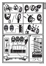
5.3 - INSTALLING AND CONNECTING THE PAIR OF
PHOTOCELLS PH100
Install the two photocells (TX = transmitting and RX = receiving) in the pre-
viously selected position. To perform the work, refer to
fig. 25
and the
instructions below.
Warning
:
Take care not to damage the O-Ring fitted
[A]
.
01.
Remove the front glass panel.
02.
Position the photocell at the point where the cables arrive.
03.
Trace the drilling points using the base as a reference Use a percus-
sion drill to drill the wall, with a 5 mm tip, and insert 5 mm plugs.
04.
Route the electric cables through the specific holes (pierce those
required): see the two options in
fig. 25-2
.
05.
Fix the base, using the relative screws
[B]
ensuring that the hole on
the base
[C]
is aligned with the cable outlet. Two additional self-tap-
ping screws are supplied for fixture on surfaces of different densities.
06.
Connect the electrical cable in the relative terminals of both TX and
RX In electrical terms, TX and RX must be connected in parallel (
fig.
25-5
); then connect the cable to the terminal “ECSBus” present on
the control unit (there is no need to observe polarity).
07.
Fix the covering
[D]
with the two screws
[E]
. Lastly insert the outer
casing
[F]
, pressing it down to secure in place.
b
c
a
1
2
22
5.4 - CONNECTING DEVICES TO CONTROL UNIT TER-
MINALS
01.
Remove the control unit from its seat with reference to the instruc-
tions in paragraph A.1 (chapter “Further details”).
02.
Adjusting the gearmotor feet.
Before proceeding, adjust the height
of the 2 feet at the rear of the gearmotor. These should touch the sur-
face of the post to increase stability of the gearmotor. These should
touch the surface of the post to increase stability of the gearmotor.
Then use a hex wrench inside the gearmotor, to make adjustments as
shown in phase 7 of
fig. 23
.
Caution!
– Never tighten the feet
more than necessary: they just need to touch the surface.
03.
Drill the rubber section of the hose connectors required and route the
connection cables through the holes.
04.
Re-connect the connector of the motor to the control unit (
caution
:
take care to observe polarity: this can only be inserted in one direc-
tion) and insert the control unit in its seat.
05.
Then refit the cable ducting support, securing it with the 4 screws.
Caution
! – Seal off any gaps to prevent the ingress of insects to the
gearmotor.
06.
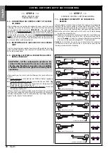
Lastly strip the cables and connect each to the dedicated terminal,
with reference to
fig. 26
and the following warnings.
• It is recommended to remove the terminals from the control unit, to
make the connections and then refit the terminals in their seats.
• Always connect the cable of the antenna and cable from the motor
without control unit in strict observance of the polarity indicated in
fig.
26
. All other connections can be made without the need to observe
polarity.
• All devices compatible with ESCBus technology must be connected
to the terminal “ESCBus” of the control unit (for further information on
the technology, read paragraph 3.3.3).
English
16
– English
Summary of Contents for WT1S
Page 11: ...1 2 3 4 45 3 1 2 a c b OK b a a b c d b a 5 6 7 8 9 10 11 12 13 13 English 10 English...
Page 14: ...OK b a 1 2 17 AA ok BB no OK 18 1 2 16 3 4 2 1 English English 13...
Page 15: ...b a 1 2 3 4 5 6 20 a b 1 2 3 4 19 English 14 English...
Page 36: ...Technical Documentation English English 35...
Page 37: ...English 36 English...
Page 39: ...English 38...
Page 41: ...English 40 English...
Page 44: ...Goniometer English English 43...
Page 45: ...44 English English Goniometer...


