background image

25

A

C

B

RX

TX

E

D

F

1

2

3

4

5

6

RX

TX

KS

100

W

T1

S

C

W

T1

SK

W

T1

S

C

W

T1

SK

PH100

PH100

FL100

fuse

Motor

connector

Connector for “PR2”  battery 
PF photovoltaic power supply

JA

JB

Led ECSbus

Led OPEN

Led STOP

Led P1

Led P2

Led P3

27

26

(control unit)

English

English – 

19

Summary of Contents for WT1S

Page 1: ...MhouseKit WT1S WT2S For power operated swing gate Installation instructions and warnings and User Manual IS0009A00EN_06 04 2011...

Page 2: ...ITTER OPERATION 21 AUTOMATION TESTING AND COMMISSIONING STEP 8 SET UP OF ELECTRICAL POWER LINE FOR PERMANENT POWER SUPPLY 22 8 1 CONNECTING THE AUTOMATION PERMANENTLY TO THE POWER MAINS 22 8 1 1 Repla...

Page 3: ...which enable declaration of presumed conformity of the automation In consideration of this all mains connection testing commissioning and maintenance operations must be performed exclusively by a qua...

Page 4: ...following a power failure black out During the power failure or at any other time the gate leafs can be moved manually if required by first releasing the gearmotor using the relative key 2 2 DEVICES A...

Page 5: ...rd or short arms the length of the arm is established during the phase prior to installa tion paragraph 3 4 if the point is located within area B the gate can be automat ed using standard length arms...

Page 6: ...s The devices used are a Electromechanical gearmotor with control unit WT1SC b Electromechanical gearmotor without control unit WT1SK c Pair of photocells PH100 wall mounted d Flashing light FL100 e K...

Page 7: ...out control unit cable 3 x 1 mm 10 m Note 1 External cable diameter Maximum 11 mm Note 2 If the power cable is longer than 30 m a cable with a larger section is required e g 3x2 5mm and safety earthin...

Page 8: ...s supplied A shorter length may be required where there is a fixed obstacle wall post etc is located behind the post where the gearmotor is to be installed preventing complete movement of the arm Ther...

Page 9: ...axis read all values of A including those between the traced horizontal lines see example in graph and where feasible select the minimum possible value This will be the required value A e On the post...

Page 10: ...is placed against the trav el stop then shake by hand to check and ensure that the gearmotor remains firmly in position If this is not so proceed as described below otherwise skip to phase 04 1 remov...

Page 11: ...1 2 3 4 45 3 1 2 a c b OK b a a b c d b a 5 6 7 8 9 10 11 12 13 13 English 10 English...

Page 12: ...the slots on the bracket fig 17 2 to enable sub sequent fine adjustments of leaf closure d Then provisionally fix the bracket on the leaf with a clamp or adhesive tape and move the leaf to the maximum...

Page 13: ...tly fixing the bracket on the leaf a Remove the slotted arm from the fixing bracket on the leaf if not already performed in phase 08 b Drill a hole in the leaf at the same point as the hole at the cen...

Page 14: ...OK b a 1 2 17 AA ok BB no OK 18 1 2 16 3 4 2 1 English English 13...

Page 15: ...b a 1 2 3 4 5 6 20 a b 1 2 3 4 19 English 14 English...

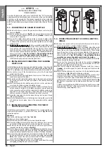
Page 16: ...b c a 9 mm max c a b c 1 2 3 4 5 6 7 8 9 10 11 12 21 CAUTION If the length of the gate post is between 80 and 135 mm the rear gearmotor fixing bracket should be turned through 90 ref paragraphs 4 1A...

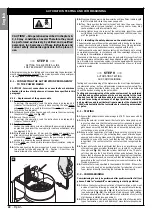
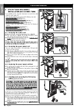
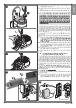
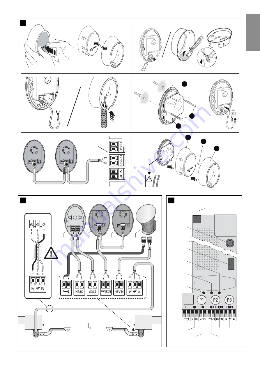
Page 17: ...ure the assembly with the relative screw 5 3 INSTALLING AND CONNECTING THE PAIR OF PHOTOCELLS PH100 Install the two photocells TX transmitting and RX receiving in the pre viously selected position To...

Page 18: ...a b a b 1 2 3 4 5 6 7 8 9 10 11 23 WT1SK gearmotor connection ref paragraph 5 1 English English 17...

Page 19: ...A B 6 mm x4 6 mm x4 1 A B 2 A B 3 A B 4 B 4 A 5 A B 6 A B 7 A B 8 A B 9 A B 11 A B 11 A B 10 A B 24 Installation and connection of FL100 flashing light ref paragraph 5 3 English 18 English...

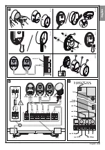
Page 20: ...5 6 RX TX KS100 WT1SC WT1SK WT1SC WT1SK PH100 PH100 FL100 fuse Motor connector Connector for PR2 battery PF photovoltaic power supply JA JB Led ECSbus Led OPEN Led STOP Led P1 Led P2 Led P3 27 26 con...

Page 21: ...to the electrical mains creating a specific power line which also includes a device to disconnect the automation from the power supply For these operations read paragraph 8 1 6 2 IDENTIFYING KEYS AND...

Page 22: ...mming the leaf movement speed The speed of the leaf during opening or closing may be set by selecting one of two options low speed or high speed To program the required option briefly press P2 and che...

Page 23: ...disconnection from the mains power and therefore must be positioned in sight of the automa tion If located in a concealed position it must be equipped with a system that prevents inadvertent or unauth...

Page 24: ...ct efficiency of all devices performing all tests and checks described in paragraph 10 1 and paragraph Maintenance operations admitted for the user appendix 3 Operation guide If other devices are pres...

Page 25: ...ow 02 Remove the connector with 5 wire plate C pulling it in the direction of the arrow 03 Lastly loosen the screws of the power terminal D and withdraw the 3 wires Caution When the connector with 5 w...

Page 26: ...rt and refit the lower cover of the gearmotor For further information on the PF device refer to its specific instruction manual A 5 1 PF application limits maximum possible number of cycles per day wi...

Page 27: ...by function is activated automatically 60 seconds after completion of an automatic manoeuvre cycle This turns off the ECSbus output and all connected devices the outputs Flash Els and all leds with th...

Page 28: ...ete when the STOP Led remains lit and Led P2 turns off Caution If Led P2 continues to flash this means that there is an error in this case read paragraph D Troubleshooting 03 Repeat the automation tes...

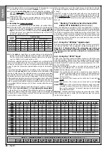
Page 29: ...t 40 seconds C MEMORISING OR DELETING RADIO TRANSMITTERS C 1 Memorising other transmitters with respect to those supplied in the kit The GTX4 transmitters supplied in the kit are already memorised and...

Page 30: ...Closure motor 1 T1 T3 No discharge T1 Once 0 1 s Minimum T1 Twice T1 Three times T1 Four times 0 4 s Medium T1 Five times T1 Six times T1 Seven times 0 7 s Maximum T1 Eight times on Opening motor 1 T...

Page 31: ...eventually a malfunction E 1 Led signals on photocells The photocells contain a LED SAFE that provides information at any moment on the state of operation For the meaning of led flashes refer to Table...

Page 32: ...board must be replaced Control unit works correctly A variation to the status of the inputs OPEN STOP activation of the photocells or when the radio transmitter is used is normal An overload has been...

Page 33: ...the manoeuvre one or more photocells do not enable movement check to see if there are any obstructions During the movement if there is an obstruction no action is required During the movement the lea...

Page 34: ...the control unit is set to receive one or more of the following commands OPEN Partial Open Only Open and Only Close Compatible GTX4 transmitters up to 256 if memorised in Mode I GTX4 transmitter range...

Page 35: ...length Up to 20 m observe warnings regarding the minimum section and type of cables Possibility of address assignment Up to 6 detectors with protection function Automatic synchronisation prevents inte...

Page 36: ...Technical Documentation English English 35...

Page 37: ...English 36 English...

Page 38: ...pendix V the product GTX4 is class 1 and marked CE0682 Models WT1SC WT1SK PH100 and FL100 conform to DIRECTIVE 2004 108 CE 108 EC OF THE EUROPEAN PARLIAMENT AND COUN CIL of 15th December 2004 regardin...

Page 39: ...English 38...

Page 40: ...Year of manufacture Location address Complies with the essential requirements of the following directives 2006 42 EC Machinery Directive 2004 108 EEC Electromagnetic compatibility directive 2006 95 E...

Page 41: ...English 40 English...

Page 42: ...ted selec tor switch If the safety devices enable this the gate will open normal ly otherwise the flashing light emits a number of flashes but the manoeuvre will not start the number of flashes depend...

Page 43: ...and turns off this means that the battery is completely discharged and must be replaced immediately Otherwise if led L1 illuminates briefly this means that the battery charge is low in this case press...

Page 44: ...Goniometer English English 43...

Page 45: ...44 English English Goniometer...

Page 46: ...Mhouse is a commercial trademark owned by Nice S p a Nice S p a Via Pezza Alta 13 Z I Rustign 31046 Oderzo TV Italia Tel 39 0422 85 38 38 Fax 39 0422 85 35 85...

Reviews: