background image

60  

Manual del Operador

OPERACIÓN

Controles antes del arranque:
Antes de empezar, controlar el nivel del aceite. (ver manual 

de motor.) Llenar el tanque de fuel en accordancia de manual 

de instruccion.
Debe revisarse el nivel del aceite de la bomba debe revisarse 

antes de cada aplicación. Revise el indicador del nivel de 

aciete en el cárter de la bomba. Asegúrese que el aciete esté 

al nivel correcto indicado por el punto en el vidrio de nivel. Use 

aceite para bombas de SAE20 o 30 no detergente si parece 

que el nivel está bajo.
Eliminar la condensación del depósito del compresor de aire.

ADVERTENCIA: PELIGRO DE LESIONES AL CU-

ERPO. NO INTENTE JAMÁS ABRIR LA VÁLVULA 

DE DESCARGA CUANDO HAY MÁS DE 10 PSI DE 

PRESIÓN EN EL INTERIOR DEL DEPÓSITO.  

Descargar la presión excesiva con una herramienta de 

aire, luego abrir la válvula de descarga del depósito de aire 

ubicada en la parte inferior del depósito. Cerrar bien una vez 

descargado.
Controlar el boton de motor es en posición de "OFF".
Controlar que la válvula de seguridad funcionando correcto.
Controlar que todas tapas y cubiertas están en posición y 

montar seguriando.OperaCiÓn
1. Leer atentamente las advertencias de seguridad antes de 

efectuar esta operación. 

2. Asegúrese que unidad toma a tierra. Vea Instrucciones de 

Conexión a Tierra.

NOTA:

 Desenchufe todo el equipo de los receptáculos de 

energía antes de comenzar la unidad.

3. Colocar muletilla que estar en la arriba de válvula pilota a 

posición vertical. Este dar una empezada sin descargar. 

Este compresor de aire puede descargar y tener una 

empezada de motor más facil.  

4. Encender el motor. (Referir a manual de este unito de motor. 

(Referir a manual de este unito de motor. En unidades de 

motor de Honda, la inductancia y la tecla del interruptor en 

el panel de la caja eléctrica.)

5. Despues de 1-2 minutos de funcionando, poner muletilla 

en posición orginal.

6. Ajustar la presión moviendo el regulador de presión en 

el sentido contrario a las manecillas del reloj para reducir 

la presión y en el sentido de las manecillas del reloj para 

aumentaria. 

7. Asegure que los cachones están en la posición de usar.
8. Examine recipiente(s) de GFCI en la unidad.  Empuje el 

botón de exam. El botón de colocar debe saltar y no debe 

tener potencia al recipiente.  Aplique una carga de examinar 

o  luz  a  cada  recipiente  para  verificar.    SI  BOTÓN  DE 

COLOCAR NO SALTE, NO USE LOS RECIPIENTES. VEA 

CONCESIONARIO PARA SERVICIO INMEDIATAMENTE.

9. Si recipientes examine correcto, empuje el botón de colocar 

para restablecer potencia.  Debe oír o sentir un taconazo 

Operación

Summary of Contents for AGW-SH22-20M

Page 1: ...TOR WELDER OPERATOR S MANUAL CAUTION RISK OF INJURY READ ENTIRE MANUAL BEFORE OPERATING THIS MANUAL IS AN IMPORTANT PART OF THE AIR COMPRESSOR GENERATOR WELDER AND MUST REMAIN WITH THIS UNIT Copyright 2011 Mi T M Corporation 37 1159 E S 092716 ...

Page 2: ... the machine The SERIAL NUMBER is located in the Specification or Identification Numbers section Accurately record all the numbers to help in tracing the machine should it be stolen Your dealer also needs these numbers when you order parts File the identification numbers in a secure place off the machine WARRANTY is provided from your dealer for customers who operate and maintain their equipment a...

Page 3: ...d to make changes at any time without notice INTRODUCTION 2 RECOGNIZE SAFETY INFORMATION 5 CONTROLS 15 16 INSTALLATION 18 OPERATION 22 START UP 22 WELDING START UP 22 SHUTDOWN 24 OPERATING CONTROLS 24 CABLE SIZE 25 TROUBLESHOOTING 26 MAINTENANCE 28 MAINTENANCE CHART 28 CHECKING ENGINE OIL 29 CHANGING ENGINE OIL 29 WIRING DIAGRAM SCHEMATIC 33 34 STORAGE 35 SPECIFICATIONS 36 WARRANTY 37 ...

Page 4: ...4 Operator s Manual Contents ...

Page 5: ... near specific hazards General precautions are listed on CAUTION safety signs CAUTION also calls attention to safety messages in this manual FOLLOW SAFETY INSTRUCTIONS Carefully read all safety messages in this manual and safety signs on your machine Keep safety signs in good condition Replace missing or damaged safety signs Be sure new equipment components and repair parts include the current saf...

Page 6: ...y from air intakes NEVER run unit inside homes garages sheds or other semi enclosed spaces These spaces can trap poisonous gases EVEN IF you run a fan or open doors and windows If you start to feel sick dizzy or weak while using the unit shut if off and get fresh air IMMEDIATELY See a doctor You may have carbon monoxide poisoning Install battery operated carbon monoxide alarms or plug in carbon mo...

Page 7: ...y on an area of bare ground While fueling the tank keep heat sparks and open flame away Carefully clean up any spilled fuel before starting engine Always fill fuel tank in an area with plenty of ventilation to avoid inhaling dangerous fumes NEVER store fuel for your unit in the home Gasoline propane kerosene and other flammable liquids should be stored outside of living areas in properly labeled n...

Page 8: ...or amps at least equal to the sum of the connected appliance loads Check that the entire cord is free of cuts or tears and that the plug has all three prongs especially a grounding pin NEVER try to power the house wiring by plugging the unit into a wall outlet a practice known as back feeding This is an extremely dangerous practice that presents an electrocution risk to utility workers and neighbo...

Page 9: ...ditional hose may be required Never fill the engine fuel tank while the engine is running or hot Allow the engine to cool two minutes before refueling Do not refuel indoors or in a poorly ventilated area Do not operate the unit if gasoline is spilled Wipe the unit clean and move it away from the spill Avoid creating any ignition until the gasoline has evaporated Do not store the unit near an open ...

Page 10: ... well ventilated area Follow all safety instructions provided with the materials you are spraying Use of a respirator may be required when working with some materials Welding produces fumes and gases Breathing these fumes and gases can be hazardous to your health Keep your head out of the fumes Do not breathe the fumes Do not weld in locations near degreasing cleaning or spraying operations The he...

Page 11: ...ssed air stream Always maintain a safe distance from people and animals while operating the unit Do not move the unit while air tank is under pressure Do not attempt to move the unit by pulling on the hose RISK FROM MOVING PARTS Risk of bodily injury from moving parts Before performing maintenance always turn off the unit Bleed pressure from the air hose and disconnect spark plug wire to prevent e...

Page 12: ...tch on electric power tools is in the OFF position before plugging them into the unit 4 Do not operate the unit or any electrical tool in any area where water or similar materials constitute an electrical hazard to the operator Do not operate on wet surfaces in rain or in snow 5 Always be sure that the unit is on secure footing so that it cannot slide or shift around endangering workers 6 Avoid co...

Page 13: ...nder your helmet Use protective screens or barriers to protect others from flash glare and sparks warn others not to watch the arc Wear protective clothing made from durable flame resistant material and foot protection Welding chipping wire brushing and grinding cause sparks and flying metal As welds cool they can throw off slag Wear approved safety glasses with side shields even under your weldin...

Page 14: ...eut pas voir ou sentir Ne JAMAIS utiliser à l intérieur d une maison ou d un garage MÊME SI les portes et fenêtres s ont ouvertes N utiliser qu à l EXTÉRIEUR et bien éloigné des fenêtres portes et conduits d aération 34 2666 34 1916 34 2666 081711 OPERATING INSTRUCTIONS FOR GENERATOR AND WELDER WARNING GENERATOR WELDER CAN CAUSE SERIOUS INJURY OR DEATH IF OPERATED IMPROPERLY BEFORE OPERATING THIS ...

Page 15: ...Welder Selector Switch 12 Min Max Weld Amperage Toggle Switch 13 Positive Welding Terminal 14 Negative Welding Terminal 15 125V Receptacle 16 125 250V 20A Twist Lock 17 Idle Control Switch 18 20A Toggle Breaker 19 20A Push Button Breaker 20 Pump Oil Sight Glass 21 Pump Oil Drain 22 Safety Relief Valve 23 Pressure Gauge 24 Regulator 25 Quick Connect 23 22 24 23 25 21 20 19 18 17 16 15 13 14 10 11 1...

Page 16: ...d Amperage Setting 12 Generator Welder Selector Switch 13 Min Max Weld Amperage Toggle Switch 14 Positive Welding Terminal 15 Negative Welding Terminal 16 Engine Choke 17 125V Receptacle 18 125 250V 20A Twist Lock 19 Idle Control Switch 20 20A Toggle Breaker 21 Engine Keyswitch 22 20A Push Button Breaker 23 Safety Relief Valve 24 Pressure Gauge 25 Regulator 26 Pump Oil Sight Glass 27 Quick Connect...

Page 17: ...W THE ENGINE OR MUFFLER TO COME IN CONTACT WITH FLAMMABLE VAPORS COMBUSTIBLE DUST GASES OR OTHER COM BUSTIBLE MATERIALS A SPARK MAY CAUSE A FIRE WHEN USING THE UNIT FOR SPRAY PAINTING PLACE THE UNIT AS FAR AWAY FROM THE WORK AREA AS POSSIBLE USING EXTRA AIR HOSES IF NEEDED Place unit at least 12 inches away from obstacles that may prevent proper ventilation Do not place unit in an area where there...

Page 18: ...rce The pipe should be 3 4 inch trade size or larger and the outer surface must be noncorrosive If a steel or iron rod is used it should be at least 5 8 inch diameter and if a nonferrous rod is used it should be at least 1 2 inch diameter and be listed as material for grounding Drive the rod or pipe to a depth of 8 feet If a rock bottom is encountered less than 4 feet down bury the rod or pipe in ...

Page 19: ...IRE ALWAYS STORE FUEL AWAY FROM THE UNIT WHILE IT IS RUNNING OR HOT WARNING RISK OF EXPLOSION OR FIRE CAUSING SERIOUS INJURY OR DEATH DO NOT ALLOW THE ENGINE OR MUFFLER TO COME IN CONTACT WITH FLAMMABLE VAPORS COMBUSTIBLE DUST GASES OR OTHER COMBUSTIBLE MATERIALS A SPARK MAY CAUSE A FIRE WHEN USING THE UNIT FOR SPRAY PAINTING PLACE THE UNIT AS FAR AWAY FROM THE WORK AREA AS POSSIBLE USING EXTRA AI...

Page 20: ...check the oil level 3 The oil level should be between the full and low marks on the dipstick Fig 2 NOTE When checking the oil be sure the engine is level 4 Fill with oil as required through the oil fill gauge opening 5 Replace the oil gauge and screw in firmly 6 Wipe up any spilled oil FUELING WARNING EXPLOSIVE FUEL GASOLINE IS EX TREMELY FLAMMABLE AND ITS VAPORS CAN EXPLODE IF IGNITED STORE GASOL...

Page 21: ...d starting Operation at an altitude that differs from that at which this engine was certified for extended periods of time may increase emissions High altitude performance can be improved by specific modifications to the carburetor If you always operate your unit at altitudes above 5 000 feet 1 500 meters have your dealer perform this carburetor modification This engine when operated at high altit...

Page 22: ...the upright position This provides a load less start The unit will unload and allow easier engine start up 4 Start the engine Refer to the Engine Manual accompanying this unit On Honda engine units the choke and key switch is located on the electric box panel 5 When the engine has run for 1 2 minutes flip toggle back to the original position 6 Set pressure by adjusting the Pressure Regulator count...

Page 23: ... Cycle 10 100 Duty Cycle 100 4 20 4 20 3 30 2 35 1 50 1 0 60 1 0 60 150 3 30 2 35 1 50 1 50 2 0 70 3 0 95 3 0 95 200 2 35 1 50 1 0 60 2 0 70 3 0 95 4 0 120 4 0 120 This chart is a general guideline and may not suit all applications If cable overheats use next size larger cable Weld cable size AWG is based on either a 4 volts or less drop or a current density of at least 300 circular mils per amper...

Page 24: ...y installed This electrical device is designed to let the engine run at fuel saving low idle speed when the generator or compressor are not loaded and at full normal governed speed when a load is applied The idle system overrides the engine governor to provide idle speed When a load is applied the electronic circuit reacts to de energize the idle system so that the engine can resume full governed ...

Page 25: ...mum cable lengths for various gauges of wire which can adequately carry the loads shown ELECTRIC MOTOR LOADS It is characteristic of common electric motors in normal operation to draw up to six times their running current while starting This table may be used to estimate the watts required to start CODE G electric motors CAUTION IF AN ELECTRIC MOTOR FAILS TO START OR REACH RUNNING SPEED TURN OFF T...

Page 26: ...lution onto all connections Check connections for air bubbles Tighten the connections where leaks are present Air leak in air tank Air tank must be replaced Do not attempt to repair air tank Defective Pilot Valve Clean or replace Insufficient pressure at air Pressure Regulator not turned to Adjust Pressure Regulator to proper tool or accessory high enough pressure or defective setting or replace R...

Page 27: ...prevent condensation buildup the unit is not run long enough Drain air tank more often in humid weather and use an air line filter Excessive oil consumption or Restricted Air Intake Filter Clean or replace oil in hose The unit on unlevel surface Do not incline the unit more than 10 in any direction while running Crankcase overfilled with oil Drain oil Refill to proper level with SAE 30W non deterg...

Page 28: ...n and every 50 hours or 3 months whichever comes first Service more frequently under dusty conditions Every 2 years an Authorized Service Technician should check the safety valve intake valves and delivery valves Procedure Daily Weekly Monthly 100 Hours 200 Hours Before Storage Check Pump Oil Level x Check Engine Oil Level x Oil Leak Inspection x Check Engine Air Filter x Drain Condensation in Air...

Page 29: ...E OR PERSONAL INJURY MAY RESULT GOVERNOR SPEED ADJUSTMENT SHOULD BE MADE ONLY BY A SERVICING DEALER CHECKING ENGINE OIL Check oil level before each operation and ensure that it is maintained per engine manual CHANGING ENGINE OIL Change oil after the first 25 hours of operation Thereafter it should be changed every 50 hours 1 Make sure the unit is on level ground Run the engine to warm the oil 2 St...

Page 30: ...ver and screw shut GENERATOR MAINTENANCE EVAPORATIVE EMISSION COMPONENTS The unit you have purchased includes the following components that are in compliance with California Air Resources Board Evaporative Emission Standards 1 Fuel Hose 2 Fuel Hose Fittings 3 Fuel Tank and Cap 4 Carbon Canister and Mounting Brackets These components should be inspected on a daily basis for cracks leaks and abnorma...

Page 31: ...rvice Representative immediately 3 High vibration or severe mechanical shock loads may cause the GFCIs to trip IF EITHER GFCI TRIPS BY ITSELF AT ANY TIME reset it and perform test procedures 1 and 2 4 Repeat steps 1 3 for the second GFCI WARNING ALTHOUGH THE ABOVE TEST PROCEDURES WILL INDICATE PROPER GFCI OPERATION ON AN UN GROUNDED OR IMPROPERLYGROUNDED GENERATOR THE GENERATOR MUST STILL BE GROUN...

Page 32: ...cedure outlined below 1 Remove the beltguard and loosen the two nuts on each side of the pump or engine There are a total of 4 nuts 2 Turn the cap screw clockwise until a 1 2 inch belt deflection is noticed between the pulleys 3 Tighten the side nuts 4 Put a straight edge across both pulleys If necessary loosen one set of pulley screws and adjust in or out to properly align Tighten the pulley scre...

Page 33: ...Maintenance Operator s Manual 33 IMPEDANCE STATOR ROTOR RECTIFIER N 1 RECTIFIER N 2 3 SWITCH 2 WELDER OUT WIRING SCHEMATIC ...

Page 34: ...34 Operator s Manual Maintenance WIRING DIAGRAM AGW SR14 30M ...

Page 35: ...Operator s Manual 35 Maintenance WIRING DIAGRAM AGW SH22 20M ...

Page 36: ... unit in a dry well ventilated place LONG TERM MORE THAN 6 MONTHS 1 Add gasoline conditioner stabilizer at the specified concentration 2 Run the unit until the fuel tank and carburetor are dry As the engine is beginning to die move the choke lever to the choke position NOTE Turn off the idle control to decrease the run time 3 Remove the spark plug pour 1 2 teaspoons 5 10cc of engine oil into the c...

Page 37: ...ltage 120 V 120 V Frequency 60 Hz 60 Hz Compressor Pump 2 stage 2 stage Pump Oil 24 7 oz 48 oz Air Tank 30 gallons 20 gallons Max Pressure 175 PSI 175 PSI RECORD SERIAL NUMBER Write your model number machine serial number and date of purchase in the spaces provided below Your dealer needs this information when ordering parts Model No __________________________________ Machine Serial No ___________...

Page 38: ...ns misapplication misuse accidents operation at other than recommended speeds pressures or temperature improper storage or freight damage Parts damaged or worn by operation in dusty environments are not warranted Failure to follow recommended operating and maintenance procedures also voids warranty 4 Labor charges loss or damage resulting from improper operation maintenance other than routine air ...

Page 39: ...igned built and equipped so as to conform with all applicable regulations and 2 is free from defects in materials and workmanship that cause the failure of a warranted part to conform with those regulations as may be applicable to the terms and conditions stated below a The warranty period begins on the date the engine is delivered to an ultimate purchaser or first placed into service The war rant...

Page 40: ...rage The following emissions warranty parts list are covered 1 Fuel Metering System A Carburetor and internal parts and or pressure regulator or fuel injection system B Air fuel ratio feedback and control system if applicable C Cold start enrichment system if applicable D Regulator assy gaseous fuel if applicable 2 Air Induction System A Intake manifold if applicable B Air filter C Controlled hot ...

Page 41: ... o números de identificación Escriba correcta todos números para ayndaría en encontrar la máquina si sea robado Su concesionario también necesite estos números cuando ordenaría partes Ponga números de identificación en lugar seguro atuera de máquina Garantía provece de concesionario Mi T M para quien opere y mantenga su equipo como describido en este manual Este manual está explicado en certificad...

Page 42: ...manual se basa en información lo último que disponible al tiempo de publicación Se reserva el dercho de efectuar combios sin previo aviso Pagiña Seguridad 43 Mandos 53 54 Instalación 55 Operación 60 Localización de fallas 65 Mantenimiento 67 Almacenamiento 75 Especificaciónes 76 Garantia 77 ...

Page 43: ...n en una lista en las señales de seguridad precaución a mensajes de seguridad en este manual SIGA LAS INSTRUCCIÓNES DE SEGURIDAD Lea con ciudado todos mensajes de seguridad en este manual y en las señales de seguridad en máquina Mantengase señales de seguridad en condición bueno Reemplace desaparecidos o señales de seguridad con daño Asegurese que componentes nuevos de equipo y partes de reparació...

Page 44: ...E el unidad al aire libre y lejos de tomas de aire NUNCA funcione el unidad dentro de hogares de garages de vertientes o de otros espacios semi enclosed Estos espacios pueden atrapar los gases venenosos INCLUSO SI usted funciona un ventilador o abre puertas y ventanas Si usted comienza a sentirse enfermo mareado o débil mientras que usa el unidad cerró si apagado y consigue el aire fresco ENSEGUID...

Page 45: ...ene el tanque solamente en una área de tierra pelada Mientras llenando el tanque mantenga calor chispas y llamas abiertas afuera Con cuidado limpie todo combustible derramado antes de empezando el motor Siempre llene tanque de combustible en una área con mucha ventilación para evite inhalando gases peligrosos NUNCA mantenga combustible para su generado e la casa Gasolina propano kerosene y otros l...

Page 46: ...as cargas de aparatos conectadas Revise que todo cordón sea libre de cortos roturas y que la tapa tiene todos los tres dientes especialamente un perno de tierra NUNCAtrate dar potencia a instalación de casa como tapando el unidad entre un tomacorriente del muro una práctica se llama alimentando atraso Esta práctica es muy peligroso que presentar un riesgo de electrocución a trabajadores de utilida...

Page 47: ... compresor de aire más de 20 pisos de ambiente de pulverizar Puede necesitar un otro tubo Nunca llenar el tanque del motor con fuel cuando motor es calor o funcionamiento Permitir el motor 2 dos minutos para enifriarse antes de más fuel No dar más fuel adentro o en ambientes con mal ventilados No funcionar el unito si hay derrames de gasolina Limpiar el compresor de aire y mover afuera de derrame ...

Page 48: ...s para los materiales que se pulverizan Al pulverizar ciertos materiales podría ser necesario usar un respirador La soldadura produce humo y gases La respiración de estos vapores y gases puede ser arriesgada a su salud Guarde su cabeza de los vapores No respire los vapores No solde en areas cerca de desengrasar limpiar o operaciones de rociar El calor y los rayos del arco pueden reaccionar con vap...

Page 49: ...r lesiones graves Con el compresor de aire en marcha mantener siempre una distancia de seguridad de presonas y animales No debe moverse el compresor de aire cuando el depósito de aire está bajo presión No intentar mover el compresor de aire tirando del tubo RIESGO DE PARTES EN MOVIMIENTO Riesgo de lesiones graves de partes en movimiento Antes de hacer mantemiento siempre parar el compresor de aire...

Page 50: ...nque de retroceso asegúrese que nada está en posición para tocar de mano o brazo de operador Asegúrese que interruptor en herramientos Eléctricos está en posición de OFF antes de los tapando entre unidad 4 No opere el unidad o alga herramienta eléctrica en área donde agua o materiales similares constituir un riesgo eléctrico a operador No opere en superficies mojados en lluvia o nieve 5 Siempre as...

Page 51: ...llo luz deslumbrante y chispas advierta a otros de no mirar el arco Lleve la ropa protectora hecha de materia duradero y resistente de llama y también lleve la protección de pie Soldando astillando cepillando de alambre y moliando causa chispas y metal volante Mientras soldadura enfrie ellos pueden tirar la escoria Lleve las gafas de seguridad aprobadas con escudos de lado bajo su casco de soldar ...

Page 52: ... ne peut pas voir ou sentir Ne JAMAIS utiliser à l intérieur d une maison ou d un garage MÊME SI les portes et fenêtres s ont ouvertes N utiliser qu à l EXTÉRIEUR et bien éloigné des fenêtres portes et conduits d aération 34 2666 34 1916 34 2666 081711 OPERATING INSTRUCTIONS FOR GENERATOR AND WELDER WARNING GENERATOR WELDER CAN CAUSE SERIOUS INJURY OR DEATH IF OPERATED IMPROPERLY BEFORE OPERATING ...

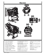
Page 53: ... Piloto 10 Ajuste de Amperaje de Soldar 11 Interruptor Seleccionador de Generador Soldar 12 Interruptor Palanca de Mínimo Máximo Amperaje 13 Enchufe de Soldar Positivo 14 Enchufe de Soldar Negativo 15 Receptáculo de 125V 16 125 250V 20A Cerradura de Torcedura 17 Interruptor de Control Inactivo 18 20A Interruptor de Palanca 19 20A Interruptor de Botón Empujado 20 Cristal de Vista del Petroleo de Bo...

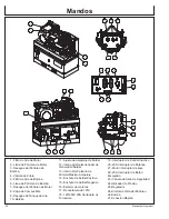
Page 54: ...oldar 12 Interruptor Seleccionador de Generador Soldar 13 Interruptor Palanca de Mínimo Máximo Amperaje 14 Enchufe de Soldar Positivo 15 Enchufe de Soldar Negativo 16 Estárter de motores 17 Receptáculo de 125V 18 125 250V 20A Cerradura de Torcedura 19 Interruptor de Control Inactivo 20 20A Interruptor de Palanca 21 Motor interruptor de llave 22 20A Interruptor de Botón Empujado 23 Válvula de Alivi...

Page 55: ...NER CONTACTO DE MOTOR Y MOEFLE CON VA PORES FLAMABLES POLVOS COMBUSTILES O OTRAS MATERIALES COMBUSTIBLES UNA CHISPA PUEDE CAUSAR UN FUEGO CUANDO USANDO EL COMPRESOR DE AIRE PARA PIN TAR PONER EL COMPRESOR DE AIRE DEMASIADO AFUERA DE AMBIENTE DE TRABAJAR USAR MÁS TUBOS DE AIRE SI NECESITAR Colocar el compresor de aire a una distancia mínima de 12 pulgadas de cualquier obstáculo que impida una corre...

Page 56: ...er resistente a la corrosión En caso de que se utilice una barra de acero o hierro el diámetro de la misma debería ser de 5 8 pulgadas como mínimo Si se utiliza una barra de un material que no sea hierro el diámetro de la misma debe ser de 1 2 pulgada como mínimo y debe estar clasificado como un material adecuado para efectuar la toma a tierra Introduzca la barra o el tubo a una profundidad de 8 p...

Page 57: ...ES GRAVES Y LA MUERTE NO TENER CONTACTO DE MOTOR Y MOEFLE CON VAPORES FLAMABLES POLVOS COMBUSTILES O OTRAS MATE RIALES COMBUSTIBLES UNA CHISPA PUEDE CAUSAR UN FUEGO CUANDO USANDO EL COMPRESOR DE AIRE PARA PINTAR PONER EL COMPRESOR DE AIRE DEMASIADO AFUERA DEAMBIENTE DE TRABAJAR USAR MÁS TUBOS DEAIRE SI NECESITAR Recomendar usar fuel del minimo de 87 octano con este compresor de aire No mezclar ace...

Page 58: ...cesario por abierta del indicador de llenado del aceite 5 Reemplace indicador del aceite y atornille firmemente 6 Limpie algo aceite derramado CARGA DE COMBUSTIBLE ADVERTENCIA EL COMBUSTIBLE ES EXPLOSIVO LA GASOLINA NAFTA ES UN FLUIDO EXTREMADA MENTE INFLAMABLE Y SUS VAPORES PUEDEN EX PLOTAR EN PRESENCIADE UNACAUSADE IGNICIÓN GUARDE EL COMBUSTIBLE EN RECIPIENTES APRO BADOS ESPECIALMENTE PARA ELLO ...

Page 59: ...e aire combustible del carburador estandard será demasiado rico Función disminuirá y consumpción de combustible aumentará Una mezcla muy rica también fallará el chispero y causar empezando difícil Operación a una altitud que es diferente de altitud donde el motor fue certificado para una extensión de mucho tiempo puede aumentar emissiones Función de altitud alta puede mejorar de modificaciones esp...

Page 60: ...ridad antes de efectuar esta operación 2 Asegúrese que unidad toma a tierra Vea Instrucciones de Conexión a Tierra NOTA Desenchufe todo el equipo de los receptáculos de energía antes de comenzar la unidad 3 Colocar muletilla que estar en la arriba de válvula pilota a posición vertical Este dar una empezada sin descargar Este compresor de aire puede descargar y tener una empezada de motor más facil...

Page 61: ...cción Localización de Averías APAGAMIENTO 1 Quite todas cargas como desconecten cordones électricos y apagadando aparatos électricos 2 Para parar el compresor de aire mover el boton de motor a posición de OFF Referir a manual de motor de este unito 3 Mueva el interruptor de GEN SOLDAR a la posición de GEN 4 Descargar el aire de los depósitos de aire por medio de una herramienta conectada o tirando...

Page 62: ...NTROL DE MARCHA EN VACÍO Nota el control inactivo es incapacitado en el modo de soldar El control de marcha en vacío viene instalado de fábrica y es un dispositivo electrónico que comanda la economización de combustible durante la marcha en vacío del motor sin carga y pasa automáticamente a marcha gobernada a velocidad normal cuando se aplican cargas eléctricas Cuando interviene el control de marc...

Page 63: ... un período de retardo de 5 a 8 segundos el motor pasará a velocidad en vacío 3 Cuando se aplica una carga al generador o la presión de tanque de compresor de aire se cae debajo de setpoint punto fijado regulado el sistema de control en vacío se desenergiza automáticamente y el motor se acelera a velocidad normal comandado por el gobernador 4 Al desconectarse la carga del generador o la presión de...

Page 64: ...DE QUE UN MOTOR NO ARRANQUE O NO ALCANCE LA VELOCIDAD NECESARIA PAR SU FUNCIO NAMIENTO DEBERÁ APAGAR INMEDIATAMENTE EL EQUIPO ELÉCTRICO O EL INSTRUMENTO PARA EVITAR DAÑOS A LOS MISMOS SIEMPRE DEBERÁ COMPROBAR LOS REQUISITOS DEL INSTRUMENTO O EQUIPO ELÉCTRICO QUE SE VA A UTILIZAR EN COMPARACIÓN CON LA CAPACIDAD NOMINAL DEL GENERADOR TAMAÑO DEL VATIOS DE VATIOS REQUERIDOS PARA ARRANCAR EL MOTOR MOTO...

Page 65: ...defectuose Fugas de aire del depósito de aire Sustituir el depósito de aire No intentar reparar el depósito Presión insuficiente en la Fugas de aire Localizar las fugas y reparar herramienta o en los accesorios Filtro aspiración aire obstruido Limpiar o sustituir Los tubos o los empalmes de los Sustituir con tubos o empalmes más tubos son demasiado pequeños grandes o largos El compresor de aire no...

Page 66: ...ustituir la bomba Compresor de aire sobre superficie No inclinar el compresor de aire no nivelada a un ángulo superior a 10 en ninguna dirección mientras esté en marcha Cárter demasiado lleno de aceite Vaciar el aceite Reponer con aceite hasta el nivel apropiado Viscocidad incorrecto Elimina el aceite Llene al nivel correcto con SAE 30W aceite sin detergente Pérdidas de aceite Apriete los pernos e...

Page 67: ...se después de 50 horas de trabajo y cada 200 horas o 3 meses según la condición que ocurra antes Se recomienda el uso de sustancias puras sin detergente Ejecutar esta tareas después de las primeras cinco 5 horas de servicio y después con la frecuencia indicada Aumentar la frecuencia si la unidad trabaja en ambientes muy polvorientos Cada dos anòs un técnico autorizado de servicio debe inspeccionar...

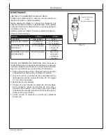
Page 68: ...as primeras 25 horas de funcionamiento y después hacerio cada 50 horas 1 Asegúrese que la unidad está en tierra nivel Opere el motor para calentar el aceite 2 Pare el motor 3 Evite tapón de descarga del aceite Fig 1 PRECAUCIÓN ELACEITE PODRÍAESTAR MUY CALIENTE TOMAR PRECAUCIONES PAR EVITAR LESIONES PER SONALES DESECHAR EL ACEITE USADO SEGÚN LOS REGLAMENTOS VIGENTES 4 Decargue aceite mientras motor...

Page 69: ...de combustible 2 Instalaciones de Manguera de combustible 3 Del tanque de combustible y la tapa 4 Carbon Canister y soportes de montaje Estos componenetes deben tener inspección en un base diario para grietas agujeros y uso abnormal Si ocurrió las grietas agujeros o uso abnormal reemplace los components inmediatamente REGULACIÓN DE VELOCIDAD DEL CONTROL DE MARCHA EN VACIO NOTA La velocidad automát...

Page 70: ...en la posición inicial y póngalo a prueba según se indica en los puntos anteriores 1 y 2 4 Para el segundo disyuntor de falla a tierra repetir los pasos 1 a 3 ADVERTENCIA AUNQUE LOS PROCEDIMIENTOS DE EXA MENARRIBAINDICARÁN OPERACIÓN CORRECTO EN UN GENERADOR BAJO TIERRAOATIERRAINCORRECTO EL GENERADOR TIENE QUE TOMAR A TIERRA DE INSTRUC CIONES DE CONEXIÓNATIERRAQUE ESTÁ EN UNALISTA DE PAGIÑA 82 PARA...

Page 71: ...e las tuercas que están a los lados de la bomba Hay un total de 4 tuercas 2 Gire el tornillo en el sentido de las manecillas del reloj hasta observar que la correa se flexiona una 1 2 pulgada 1 3 cm entre las poleas 3 Apriete las tuercas laterales 4 Ponga una regla tocando el costado de ambas poleas Si es necesario afloje los tornillos de una polea y muévala hacia adentro o hacia afuera para que q...

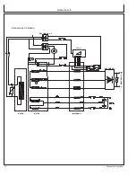
Page 72: ...72 Manual del Operador Mantenimiento IMPEDANCE STATOR ROTOR RECTIFIER N 1 RECTIFIER N 2 3 SWITCH 2 WELDER OUT Esquema de Cableado ...

Page 73: ...Manual del Operador 73 Mantenimiento Diagrama de Cableado AGW SR14 30M ...

Page 74: ...74 Manual del Operador Mantenimiento Diagrama de Cableado AGW SH22 20M ...

Page 75: ... lugar seco y bien ventilado A LARGO PLAZO MÁS DE 6 MESES 1 Agregue acondicionador y estabilizador de combustible con la concentración adecuada 2 Ponga en marcha la unidad hasta se consuma el combustible en el tanque y en el carburador Cuando el motor está aminorando la marcha lleve la palanca del cebador a la posición de cebado NOTA Anular el control de marcha en vacío para reducir el tiempo en m...

Page 76: ...a 60 Hz 60 Hz Bomba Compresor Doble Fase Doble Fase Aceite 0 73 L 1 42 L Depósito Aire 113 5 L 88 L Presión máximo 175 PSI 175 PSI Especificaciónes ANOTE NÚMERO SERIE Escriba número de modelo numero serie de máquina vea etiqueta de número serie A en ilustración y fecha de compra en espacios abajo Su concesario necesita esta información cuando ordenando partes Num de modelo_________________________...

Page 77: ...a aplicación mal uso operación a velocidades presiones o temperaturas diferentes a las recomendadas Las piezas dañadas o gastadas a causa del uso de líquidos cáusticos o por la operación en medios ambientes abrasivos o corrosivos o bajo condiciones que causan cavitación de la bomba no están garantizadas La falla en seguir los procedimientos recomendados de operación y mantenimiento también cancela...

Page 78: ... T M en 1 800 553 9053 o por correo electrónico a corp mitm com COBERTURA GENERAL DE GARANTIA DE EMISIONES Sólo California Mi T M justifica al último comprador y cada comprador subsiguiente que el Pequeño Motor Todoterreno PMT 1 ha sido diseñado construido y equipado para conformarse con todas regulaciones aplicables y 2 es libre de defectos en materias y disfraza que causa el fracaso de una pieza...

Page 79: ...ión de ajuste que ha sido instalado por la fábrica y está funcionando apropiadamente todavía está elegible para la cobertura de la garantía Las siguientes piezas de garantía de emisiones están garantizadas 1 Sistema de Medir Combustible A Carburador y partes internos y o el regulador de presión o sistema de inyección B Retroalimentación de Aire Combustible y sistema de control si aplicable C Siste...

Page 80: ...80 Manual del Operador Manufactured by Mi T M 50 Mi T M Drive Peosta IA 52068 563 556 7484 Fax 563 556 1235 ...

Reviews: