background image

14  

Operator’s Manual

GROUNDING INSTRUCTIONS

This product must be grounded.  If it should malfunction or 

breakdown, grounding provides a path of least resistance for 

electric current to reduce the risk of electric shock.  


DANGER - IMPROPER CONNECTION OF THE  


  EQUIPMENT-GROUNDING CONDUCTOR CAN  


  RESULT IN A RISK OF ELECTROCUTION.   


  CHECK WITH A QUALIFIED ELECTRICIAN OR    


  SERVICE PERSON IF YOU ARE IN DOUBT AS  


  TO WHETHER THE UNIT IS PROPERLY    


   GROUNDED. 

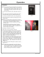
The wing nut and ground terminal on the frame must always 

be used to connect the generator to a suitable ground source. 

The ground path should be made with #8 size wire. Connect the 

terminal of the ground wire between the two star washers and 

wing nut then tighten the wing nut fully. Connect the other end 

of the wire securely to a suitable ground source.

The National Electric Code contains several practical ways in 

which to establish a good ground source. Examples given below 

illustrate a few of the ways in which a good ground source may 

be established.

A metal underground water pipe in direct contact with the earth 

for at least 10 feet can be used as a grounding source. If an pipe 

is unavailable, an 8 foot length of pipe or rod may be used as the 

ground source. The pipe should be 3/4 inch trade size or larger 

and the outer surface must be noncorrosive. If a steel or iron rod 

is used it should be at least 5/8 inch diameter and if a nonferrous 

rod is used it should be at least 1/2 inch diameter and be listed 

as material for grounding. Drive the rod or pipe to a depth of 8 

feet. If a rock bottom is encountered less than 4 feet down, bury 

the rod or pipe in a trench. All electrical tools and appliances 

operated from this generator, must be properly grounded by use 

of a third wire or be “Double Insulated”. 

It is recommended to:

1. 

Use electrical devices with 3 prong power cords.

2.    Use an extension cord with a 3 hole receptacle and a 3  


prong plug at the opposite ends to ensure continuity of  


the ground protection from the generator to appliance.

We strongly recommend that all applicable federal, state and 

local regulations relating to grounding specifications be checked 

and followed. 

Preparing the Generator

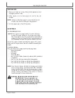
LINE TRANSFER SWITCH

If this generator is used for standby service, it must have 

a transfer switch between the utility power service and the 

generator. The transfer switch not only prevents the utility 

power form feeding into the generator, but is also prevents the 

generator form feeding out into the utility company’s lines. This 

is intended to protect the serviceman who may be working on 

a damaged line. 

THIS INSTALLATION MUST BE DONE BY A LICENSED 

ELECTRICIAN AND ALL LOCAL CODES MUST BE 

FOLLOWED.

GND

34-0889

062104-ENG.

Summary of Contents for GEN-13000-1MSE

Page 1: ... RISK OF INJURY READ ENTIRE MANUAL BEFORE OPERATING THIS MANUAL IS AN IMPORTANT PART OF THE GENERATOR AND MUST REMAIN WITH THIS UNIT Copyright 2009 Mi T M Corporation OPERATOR S MANUAL FOR GEN 13000 1MSE GEN 14000 1MHE GENERATORS ...

Page 2: ...also needs these numbers when you order parts File the identification numbers in a secure place off the machine WARRANTY is provided from your dealer for customers who operate and maintain their equipment as described in this manual The warranty is explained on the warranty certificate shown in this manual This warranty provides you the assurance that your dealer will back products where defects a...

Page 3: ...r 14 Operation 18 Troubleshooting 22 Service 23 Storage 29 Specifications 30 Warranty 31 33 All information illustrations and specifications in this manual are based on the latest information available at the time of publication The right is reserved to make changes at any time without notice ...

Page 4: ...4 Operator s Manual Contents ...

Page 5: ...recautions are listed on CAUTION safety signs CAUTION also calls attention to safety messages in this manual FOLLOW SAFETY INSTRUCTIONS Carefully read all safety messages in this manual and safety signs on your machine Keep safety signs in good condition Replace missing or damaged safety signs Be sure new equipment components and repair parts include the current safety signs Replacement safety sig...

Page 6: ...s not sufficient to carry away exhaust fumes Exhaust fumes can cause serious injury or death NEVER use a generator indoors including in homes garages basements crawl spaces and other enclosed or partially enclosed areas even with ventilation Opening doors and windows or using fans will not prevent carbon monoxide build up in the home Follow the instructions that come with your generator Locate the...

Page 7: ...UND FAULT CIRCUIT INTERRUPTER PROTECTION These generators are equipped with three GFCI Ground Fault Circuit Interrupters 120V duplex receptacles for protection against the hazards of electrical shock from defective attachments such as tools cords and cables WARNING The GFCIs may not function unless the generator is properly grounded Follow the correct procedure specified in the section labeled GRO...

Page 8: ...ach use see Operations Instructions for further information If GFCI fails test DO NOT use your generator Contact your Mi T M Customer Service Representative Plug appliances directly into the generator Or use a heavy duty outdoor rated extension cord that is rated in watts or amps at least equal to the sum of the connected appliance loads Check that the entire cord is free of cuts or tears and that...

Page 9: ...nerator 4 Do not operate the generator when fatigued or under the influence of drugs or chemicals Stay alert Watch what you are doing 5 Follow the maintenance instructions specified in this manual 6 Block the wheels to prevent the unit from moving while operating Always make sure the unit is level and properly grounded 7 Be sure the switch on electric power tools is in the OFF position before plug...

Page 10: ... Preparing the Generator Grounding Instructions Tools and appliances which have 3 prong plugs must be plugged into extension cords and electrical receptacles with 3 holes Before operating any electrical item be sure it is in good repair 14 Follow instructions in this manual when testing Ground Fault Circuit Interrupter to insure reliable operation 15 Beware of using this equipment in confined spac...

Page 11: ...ds and shields are tight and in place Locate all operating controls and safety labels Inspect power cord for damage before using There is a hazard of electrical shock from crushing cutting or heat damage PREPARE FOR EMERGENCIES Keep a first aid kit and fire extinguisher handy Keep emergency numbers for doctors ambulance service hospital and fire department near your telephone Be prepared if a fire...

Page 12: ...enfriarse por dos 2 minutos No permitando enfriarse del motor puede resultar en daño a la unidad 3 Gire el interruptor del motor a la posición OFF DEMARRAGE 1 Tourner l interrupteur de la commande de ralenti sur la position arrêt OFF 2 Placer la manette du starter en position maximum 3 Placer la clé sur la position DEMARRAGE et la maintenir sur cette position jusqu à ce que le moteur démarre 4 Lor...

Page 13: ...Operator s Manual 13 Controls CONTROLS A Control Panel B Brake C Fuel Tank D Muffler E Lift Hook A C B D E ...

Page 14: ...de size or larger and the outer surface must be noncorrosive If a steel or iron rod is used it should be at least 5 8 inch diameter and if a nonferrous rod is used it should be at least 1 2 inch diameter and be listed as material for grounding Drive the rod or pipe to a depth of 8 feet If a rock bottom is encountered less than 4 feet down bury the rod or pipe in a trench All electrical tools and a...

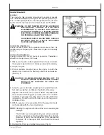
Page 15: ...E TO FILL IT BEFORE OPERATING THE ENGINE ENGINE OIL CAPACITY To fill with oil 1 Level the engine to ensure accurate inspection and to prevent overfilling 2 Remove the dipstick and wipe it clean 3 Fully insert the dipstick then remove it to check the oil level 4 If the oil level is low remove the oil filler cap and fill to the upper limit mark on the dipstick with the recommended oil Fig 2 5 Reinst...

Page 16: ...endations Purchase gasoline in small quantities and store in clean approved containers To minimize gum deposits in your fuel system and to insure easy starting do not use gasoline left over from the previous season Do not add oil to the gasoline Fuel Type For best results use only clean fresh unleaded gasoline with a pump sticker octane rating of 87 or higher Unleaded gasoline is recommended as it...

Page 17: ...our dealer perform this carburetor modification This engine when operated at high altitude with the carburetor modifications for high altitude use will meet each emission standard throughout its useful life Even with carburetor modification engine horsepower will decrease about 3 5 for each 1 000 foot 300 meter increase in altitude The effect of altitude on horsepower will be greater than this if ...

Page 18: ... Do not make further attempts to start the engine until the condition is corrected Do not jump start using another battery 5 Slowly move choke lever to no choke 6 Allow unit to run two 2 minutes to warm up 7 Test the GFCI receptacle s on the unit Push the test button The reset button should pop out and there should be no power at the receptacle Apply a test load or lamp to each receptacle to verif...

Page 19: ...evel the engine then check the oil before restarting the engine CONTROL PANEL The generators are equipped with the following items Idle Control Switch Hour Meter Volt Meter Circuit Breakers Two 125 Volt 20 Amp Duplex 2 outlets GFCI protected receptacles One 125 Volt 30 Amp Locking Type Receptacle One 125 250 Volt 30 Amp Locking Type Receptacle One 125 250 Volt 50 Amp Locking Type Receptacle NOTE T...

Page 20: ...electronic circuit reacts to de energize the idle system so that the engine can resume full governed operating speed The idle control system controls the engine speed in the following manner 1 With the idle control switch in the OFF position start the engine 2 After one or two minute warm up period apply load and move the switch to the ON position The engine will throttle back to idle speed follow...

Page 21: ...es the maximum cable lengths for various gauges of wire which can adequately carry the loads shown ELECTRIC MOTOR LOADS It is characteristic of common electric motors in normal operation to draw up to six times their running current while starting This table may be used to estimate the watts required to start CODE G electric motors CAUTION IF AN ELECTRIC MOTOR FAILS TO START OR REACH RUNNING SPEED...

Page 22: ...om around the plug base then remove the spark plug Install the spark plug in the plug cap Turn the engine switch on Grounding the electrode to any engine ground pull the recoil starter to see if sparks jump across the gap If there is no spark replace the plug Reinstall the plug and start engine according to instructions in this manual Consult Mi T M Customer Service Generator has no output Circuit...

Page 23: ...THE DUPLEX RECEPTACLE Have the unit serviced by an authorized Mi T M Customer Service Representative immediately 3 High vibration or severe mechanical shock loads may cause the GFCIs to trip IF EITHER GFCI TRIPS BY ITSELF AT ANY TIME reset it and perform test procedures 1 and 2 4 Repeat steps 1 3 for the second GFCI WARNING ALTHOUGH THE ABOVE TEST PROCEDURES WILL INDICATE PROPER GFCI OPERATION ON ...

Page 24: ...components should be replaced immediately IDLE CONTROL ADJUSTMENT NOTE The automatic idle speed is set between 2550 and 2950 RPM The idle speed has been pre set at the factory and should rarely require readjustment We recommend that all adjustments of this nature be made by a Mi T M Customer Service Representative Erratic idle operation of the engine usually indicates a need for carburetor adjustm...

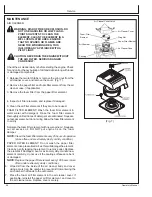
Page 25: ...quickly and completely 2 Stop the engine 3 Place a suitable container below the engine to catch the used oil then remove the filler cap drain bolt and washer See Fig 5 CAUTION OIL BEING DRAINED MAY BE HOT TO REDUCE THE RISK OF BURN INJURY HANDLE WITH CARE DISPOSE OF USED OIL PROPERLY 4 Allow the used oil to drain completely then reinstall the drain bolt and new washer and tighten the drain bolt se...

Page 26: ... traces of detergent are eliminated Squeeze out excess water but do not wring Allow the foam filter element to air dry Saturate the foam filter element with new engine oil Squeeze out all excess oil DO NOT put engine oil on the foam damper NOTE Clean the foam filter element every 25 hours of operation more often under extremely dusty or dirty condition PAPER FILTER ELEMENT Do not wash the paper fi...

Page 27: ...in some states must comply with fire prevention regulations Clean the spark arrester as follows Fig 9 and 10 1 Remove the screw from the muffler and remove the spark arrester 2 Use a brush to remove carbon deposits from the spark arrester screen Be careful to avoid damaging the screen The spark arrester must be free of breaks and holes Replace the spark arrester if it is damaged 3 Install the spar...

Page 28: ... Before 25hrs 100 hrs 200 hrs Storage Check fuel Check engine oil Check for loose or lost nuts and bolts Check for leaks Check cylinder and head fins for dust and dirt Check fuel lines replace if necessary Clean air cleaner foam element Tighten nuts and bolts Change engine oil Clean fuel filter Replace air cleaner paper element Clean dust and dirt from cylinder and cylinder head fins Clean and reg...

Page 29: ...rator in a dry well ventilated place LONG TERM More than 6 months 1 Add gasoline conditioner and stabilizer at the specified concentration 2 Run the generator until the fuel tank and carburetor are dry As the engine is beginning to die move the choke lever to the choke position NOTE Turn off the idle control to decrease the run time 3 Remove the spark plug pour 1 2 teaspoons 5 10cc of engine oil i...

Page 30: ...needs this information when ordering parts Model No _______________________________________________ Machine Serial No ________________________________________ Date of Purchase_________________________________________ To be filled in by purchaser NOTE Unit ratings are established based on operation at standard conditions of 60 F and at sea level The performance of the generator must be de rated for...

Page 31: ...edduetonormalwear misapplication misuse operation at other than recommended Failure to follow recommended operating and maintenance procedures also voids warranty 3 The use of other than genuine manufacturer repair parts will void warranty 4 Parts returned prepaid to our factory or to anAuthorized Mi T M Service Center will be inspected and replaced free of charge if found to be defective and subj...

Page 32: ...s and conditions stated below a The warranty period begins on the date the engine is delivered to an ultimate purchaser or first placed into service The warranty period is two years b Subject to certain conditions and exclusions as stated below the warranty on emissions related parts is as follows 1 Any warranted part that is not scheduled for replacement as required maintenance in your owner s ma...

Page 33: ... for repair or replacement of the part That notwithstanding any adjustment of a component that has a factory installed and properly operating adjustment limiting device is still eligible for warranty coverage The following emissions warranty parts list are covered 1 Fuel Tank 2 Fuel Cap 3 Fuel Lines for liquid fuel and fuel vapors 4 Fuel Line Fittings 5 Clamps 6 Pressure Relief Valves 7 Control Va...

Reviews: