background image

Mi-T-M

 WOS-SERIES Operator's Manual 


3

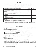
pRE-OpERaTION CHECKlIST

STop

TO ENsURE yOUR WATER RECyClE TREATmENT sysTEm OPERATEs sAfEly AND 

EffICIENTly, COmPlETE ThE PRE-OPERATION ChECklIsT bEfORE PROCEEDING.

prEparaTion

prE-STarT proCEDUrES:

.  Open the 

Pit Return Valve 3

 and close the 

Water Outlet Valve 2

 to allow water to flow back to the pit for continual 

recycling.

2.  Be certain all hoses are securely connected. 
3.  Be certain the incoming air tube to the 

ozone Generator (5)

 is not obstructed.

WX-OPTION:

   Be certain all switches on the 

Control panel (23) 

are in the "OFF" position.

4.  plug the pump plug into the piggyback plug and then into the grounded outlet on the 

Control panel (23)

.

5.  plug the power supply cord into a grounded outlet.  Turn on the 

power Supply Switch (21)

.  

STarT-Up:

1.  Ensure the pit is filled with water.
2.  Turn on the 

Sump pump Switch (22)

.  Water will flow into the 

oil/Water/Solids Separator (7)

.

3.  Turn on the switch located on the 

ozone Generator (5)

.

4.  Flow  can be increased by opening the 

Water Inlet Flow Control Valve 1.

  Fill the 

oil/Water/Solids Separator (7)

.

5.  As the water fills the 

Holding Tank (14)

, it will begin to flow out the 

Overflow Drain (15)

 at the top of the tank.  at 

this point, flow can be adjusted with the 

Water Inlet Flow Control Valve 1

.  Maximum flow is achieved when the water 

level remains constant in the 

Holding Tank (15)

.

6.  Water is now completely cycled in the system.

Before proceeding, answer all the questions on this checklist.   


  yES   

  NO

CoDES:

.  Does the electrical wiring meet all codes?

2.  Does plumbing meet all codes?

LoCaTion:

1.  Is the unit located on a hard level surface free of flammable vapors,  

  combustible dust, gases or other combustible materials?

2.  Is the unit located in a large ventilated area?

ELECTriCaL:

.  Is the unit properly grounded?

2.  Does the power supply, voltage and amperage match the data plate?

pLUmBinG:

.  Is the plumbing sized correctly?

2.  Is the check valve installed near the 

Sump pump (4)

?

3.  are all  unions tightened?

GEnEraL:

.  Have all operators using this unit read and understood this entire manual?

2.  Has the unit been installed by qualified service people who followed the  

  instructions listed in this manual?

iF "no" WaS marKED To anY oF THESE QUESTionS, CorrECT THE SiTUaTion BEForE opEraTinG.

WARNING


riSK oF ELECTroCUTion!  To rEDUCE THE riSK oF ELECTroCUTion, KEEp aLL 

ConnECTionS DrY anD oFF THE GroUnD.  

Summary of Contents for WOS-SERIES

Page 1: ...T M WOS SERIES OIL WATER SOLIDS SEPARATOR Copyright 2005 Mi T M Corporation Form 37 0523 091505 CAUTION RISK OF INJURY READ MANUAL BEFORE OPERATING This manual is an important part of the Oil Water Solids Separator and must remain with the unit when you sell it ...

Page 2: ...K OF EXPLOSION OR FIRE 6 RISK OF BURSTING 6 RISK OF BURNS 6 RISK FROM MOVING PARTS 7 RISK OF BODILY INJURY 7 flow CHART 8 9 FEATURES 10 11 INSTALLATION 12 13 attire 12 installation 12 PRE START CHECKLIST 13 PREPARATION 13 PRE START PROCEDURES 13 START UP 13 OPERATION 14 BEGIN 14 MAINTENANCE 14 Waste Oil Decanter 14 SOLIDS COLLECTION AREA 14 WINTERIZING 14 TROUBLESHOOTING 15 16 NOTES 17 18 STATEMEN...

Page 3: ... avoided WILL result in death or serious injury WARNING Indicates a potentially hazardous situation which if not avoided COULD result in death or serious injury CAUTION Indicates a potentially hazardous situation which if not avoided MAY result in minor or moderate injury The symbol set to the left of this paragraph is a Safety Alert Symbol This symbol is used to call attention to items or procedu...

Page 4: ...your WOS Series Oil water solids separator 1 Sump Pump 2 Unattached Float with Piggy Back Plug for Sump Pit 3 Oil Water Solids Separator Platform a Ozone Generator b Oil Water Solids Separator 4 Manual specifications MODEL WOS 15 WOS 30 MAXIMUM FLOW 15 GPM 30 GPM ELECTRICAL 115 V 1 Phase 15 Amps 115 V 1 Phase 15 Amps SUMP PUMP 1 2 HP 1 2 HP OIL WATER SOLID SEPA RATOR CAPACITY 170 Gallons 340 Gallo...

Page 5: ...grounded Always be certain the unit is receiving proper voltage 5 of the voltage listed on the nameplate Before installing electrical connections be certain the power switches are in the OFF position Keep all connections dry and off the ground Do not touch pump pump motor discharge piping or water when the unit is connected to the power supply regardless of whether the unit is operating correctly ...

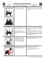
Page 6: ... all protective covers in place Follow the maintenance instructions specified in the manual RISK FROM MOVING PARTS Serious injury may occur from touching the electrical motor This area can remain hot for some time after the oil water solids separator is shutdown RISK OF BURSTING Serious injury or death could occur from bursting caused by excessive pressure in the system Serious injury may occur if...

Page 7: ... DO NOT DRINK THE WATER IN THE OIL WATER SOLIDS SEPARATOR This is non potable water and is not suitable for consumption DO NOT allow children to operate this unit DO NOT overreach or stand on unstable support Wet surfaces can be slippery wear protective foot gear and keep good footing and balance at all times Knowhowtostoptheoil water solidsseparator Be thoroughly familiar with controls Before ser...

Page 8: ... Mi T M WOS SERIES Operator s Manual wOS 0001 062105 ASY oil water separator system flow chart ...

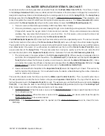
Page 9: ...ing too quickly over the 1st weir under the 2nd weir and into the bottom of the Separator Tank 9 which is composed of a horizontal Oil Coalescing Grid 10 1 The oil molecules in the water adhere to the Oil Coalescing Grid 10 When enough oil molecules attach to each other the oil droplets float to the surface The Oil Skimmer 11 is positioned near the top of the Separator Tank 9 which allows the thin...

Page 10: ... shown on pg 8 5 Ozone Generator 6 Ozone Injector 7 Oil Water Solids Separator 8 Ozone Contact Tank 9 Separator Tank 10 Oil Coalescing Grid 11 Oil Skimmer 12 Waste Oil Decanter 13 Water Level Control Tank 14 Holding Tank 15 Overflow Drain 16 Tank Lid 17 Outlet Return to Pit 18 Inlet from Sump Pump 19 Level Limit Switch 20 Sump Pump Receptacle 21 Power Supply Switch On Off 22 Power Cord w 20 Amp Pl...

Page 11: ...OS SERIES Operator s Manual 11 FEATURES VIEW wOS 30 WOS 30 0M10 062105 ASY Water Inlet Flow Control Valve 1 Water Outlet Valve 2 Pit Return Valve 3 Oil Release Valve 4 Actuated Ball Valve 5 valves Wos 15 wos 30 ...

Page 12: ...shipping damage Tighten all union connections at this time 5 Hook up the Inlet From Sump Pump 18 and Outlet Return To Pit 17 plumbing The WOS 15 and WOS 30 is shipped with male cam and groove fittings pre installed a Install the Sump Pump 4 near the Sump Pit 3 b Install plumbing from Sump Pump 4 using minimum connection sizes as listed WOS 15 WOS 30 2 c Install a check valve near the outlet plumbi...

Page 13: ...he water fills the Holding Tank 14 it will begin to flow out the Overflow Drain 15 at the top of the tank At this point flow can be adjusted with the Water Inlet Flow Control Valve 1 Maximum flow is achieved when the water level remains constant in the Holding Tank 15 6 Water is now completely cycled in the system Before proceeding answer all the questions on this checklist YES NO CODES 1 Does the...

Page 14: ...ither situation do not use pressure washers while performing this maintenance 1 Using 2 PVC plumb a discharge line with a shut off valve from the solids collection area back to the Wash Water Catch Pit 1 or other settling area This will allow manual control of solids flow out of the oil water separator system eliminating the need to stop the unit and clean the Separator Tank 9 2 The unit will need...

Page 15: ...n valve clockwise to reduce flow Sump Pump 4 impeller is clogged Disconnect power and unclog impeller Motor overload Allow motor to cool Motor will automatically restart when cool Sump Pit 3 is not large enough Expand size of pit Sump Pump 4 runs but there is In line wye strainer is plugged Clean repair or replace little or no water discharge Water level is below pump inlet Ensure Float 1 is not c...

Page 16: ... valve Clean Sump Pump 4 impeller is clogged Disconnect power and clean Lines or valves contain frozen water Allow to thaw Inject with warm water if necessary SHAFT SEALS Water is leaking at pumps Damaged stationary shaft seal Seal ran dry Ensure seal chamber is filled with liquid Short seal life Unexpected temperature and Replace chemical usage WATER FLOW Air shoots from Water Outlet This is a co...

Page 17: ...Mi T M WOS SERIES Operator s Manual 17 NOTES ...

Page 18: ...18 Mi T M WOS SERIES Operator s Manual NOTES ...

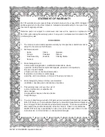
Page 19: ...abuse operation at other than recommended speeds pressures or temperature the use of caustic liquids chloride corrosion or chemical deterioration fluctuations in electrical or water supply operating unit in an abrasive corrosive or freezing environment 4 Parts damaged by failure to follow recommended installation operating and maintenance procedures 5 This warranty does not cover the cost of norma...

Page 20: ...20 Mi T M WOS SERIES Operator s Manual Manufactured by Mi T M 8650 Enterprise Drive Peosta IA 52068 563 556 7484 Fax 563 556 1235 ...

Reviews: