Instruction Manual MIC type EC-912
Revision no.4
12 / 38
b)
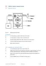
Interconnect a PC and the IMCU with a RJ45 LAN cable or USB cable.
c)
From a Web browser enter the MIC Webpage by selecting the address 172.16.99.100.
OBS You might need to force your PC to scan the IP range from IP 172.16.99.50 (in network
preferences TCP/IPV4).
The following web-page appears:
d)
The calibration is initiated by pressing the Start
button. The LED “Calibrate” on the IMCU turns
ON.
The Calibrate button should only be pressed, when the Measuring Ionization Chamber, MIC, is
known to contain clean aerosol free air.
When the calibration is done and the MIC system is ready for normal operation, the Last
Calibrated time stamp is updated.
i)
Connect the vacuum pump (VP) and air outlet on the rear of the Flow Control Unit (FCU) with a
piece of hose.
j)
Turn the flow meter needle valve in the FCU fully C.W.
k)
Connect the VP to the mains and switch on power. The ball in the flow meter on the FCU shall
stay in its lowest position.
l)
Turn the flow meter needle valve C.C.W. until the middle point of the ball
indicates approx. 30 1/min. Block the air inlet on the rear panel of the FCU with a finger and
control that the ball drops to its lowest position. Fasten the finger screws on the filter unit and
checks for leaks if this does not happen.


