XZR200 User’s Manual
8
97337 Issue 4, July 2018
INSTALLATION
3.3
System Block Diagram
V
V
RS232 Rx RS232 Tx
PC or RS232
SERIAL DEVICE
RS232 GND
CYCLE
MONITOR
GND
External Calibration
Switch
4-20mA
(Pin 4)
0 - 10 V DC
(Pin 3)
OR
RS232 Tx
(Pin 4)
RS232 Rx
(Pin 3)
XZR
200
OXYGEN ANALYZER
CYCLE
(Pin 5)
CALIBRATE
(Pin 6)
+24 V DC
(Pin 1)
100 to
600Ω
GND
(Pin 7)
+
-
+
24 V DC
POWER
SUPPLY
Figure 5
System Block Diagram
3.4
RS232 Communication Settings
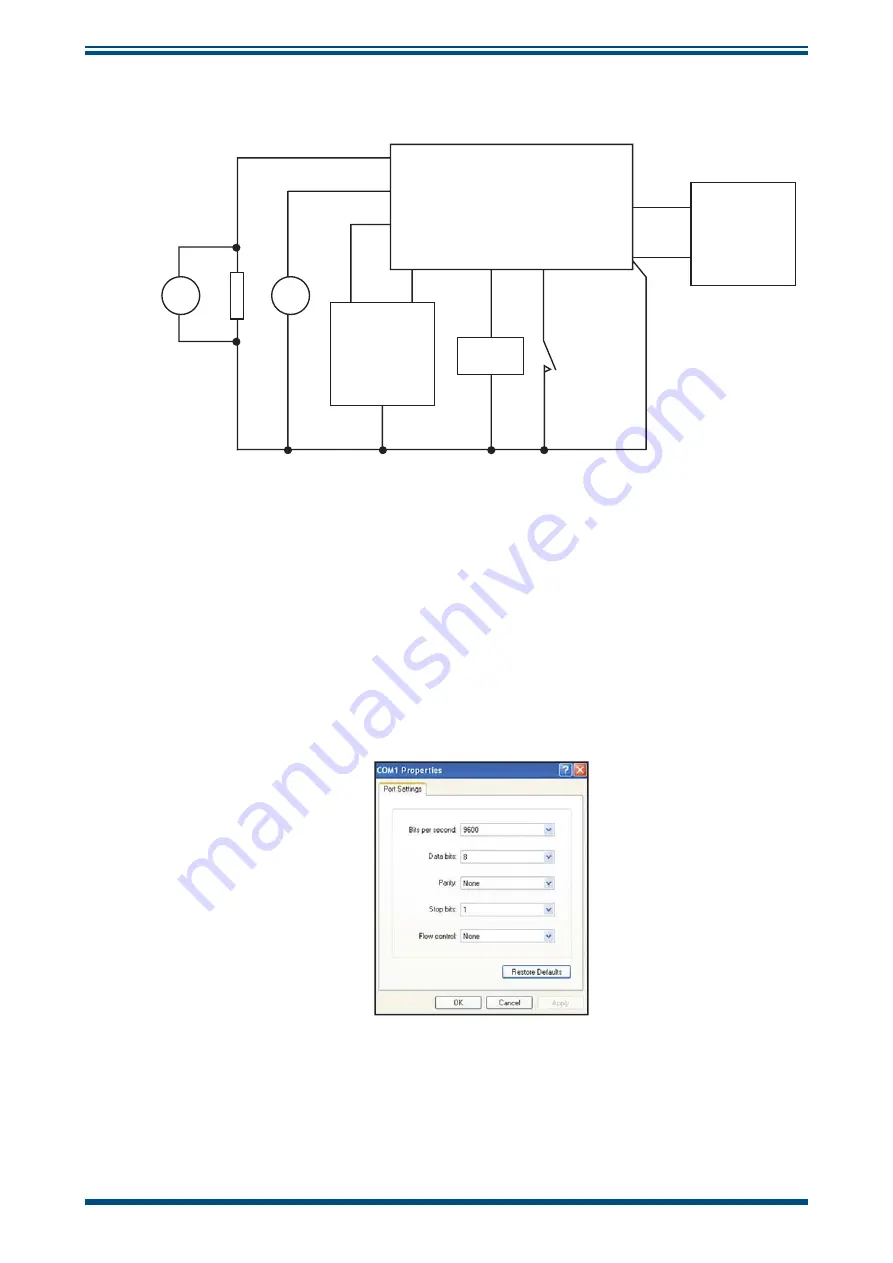
When connecting the XZR200 via the RS232 connections, ensure Tx goes to Rx of the
PC and Rx goes to Tx of the PC.
The XZR200 communicates via standard COM port settings that are default on most
PC's and many other RS232 compatible devices. If, however, communication problems
are occurring, the settings below can be used to con
fi
gure the PC or device COM Port.
Figure 6
COM Port Settings
Summary of Contents for XZR200
Page 1: ...XZR200 Oxygen Analyzer User s Manual 97337 Issue 4 July 2018 ...
Page 24: ...XZR200 User s Manual Michell Instruments 17 CALIBRATION Appendix A Technical Specifications ...
Page 27: ...XZR200 User s Manual 20 97337 Issue 4 July 2018 APPENDIX B Appendix B Theory of Operation ...
Page 35: ......
Page 36: ...http www michell com ...


