81
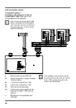
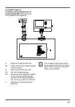
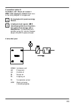
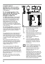
Connection option 2:
Ventilation unit with digital room air
control RLS D1 WR.
Refer also to the
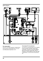
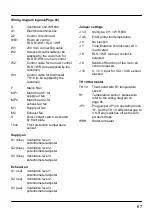
wiring diagram in the appendix.
A
Electrical terminal box WR 600
A2
Control circuit board: Jumper 8 bridged
= factory setting
B
Room air control RLS D1 WR
W1
230 VAC connecting cable
W2
Screened control cable (to be supplied
by the customer) for RLS D1 WR
room air control. External diameter
3.2...6.5 mm, e.g. LIYCY 2 x 0.75 mm²
V
Distributor (to be supplied by the
customer)
The ventilation unit is factory-set for
the connection of the room air control
RLS D1 WR. Jumper 8 is set on the
control circuit board A2.
i
Summary of Contents for aeronom WR 600
Page 6: ...4...
Page 50: ...48 15 Anhang Verdrahtungsplan...
Page 52: ...50...
Page 56: ...54 Exhaust air Supply air Outgoing air Outside air...
Page 100: ...98 15 Appendix Wiring diagram...
Page 102: ...100...
Page 106: ...104 Air sortant Air entrant Air rejet Air ext rieur...

