3.14
Self-Monitoring (Function Group SFMON)
Comprehensive monitoring routines in the P631 ensure that internal faults are
detected and do not lead to malfunctions. The selection of function assignments
to the alarm signal includes, among others, self-monitoring signals from the
communications monitor, measuring-circuit monitoring, open-circuit monitoring
and the logic outputs.
3.14.1
Tests During Start-up
After the supply voltage has been turned on, various tests are carried out to
verify full operability of the P631. If the P631 detects a fault in one of the tests,
then start-up is terminated. The display shows which test was running when
termination occurred. No control actions may be carried out. A new attempt to
start up the P631 can only be initiated by turning the supply voltage off and then
on again.
3.14.2
Cyclic Tests
After start-up has been successfully completed, cyclic self-monitoring tests will
be run during operation. In the event of a positive test result, a specified
monitoring signal will be issued and stored in a non-volatile(NV) memory – the
monitoring signal memory – along with the assigned date and time (see
).
The self-monitoring function monitors the built-in battery for any drop below the
minimum acceptable voltage level. If the associated monitoring signal is
displayed, then the power supply module should be replaced within a month,
since otherwise there is the danger of data loss if the supply voltage should fail.
gives further information on maintenance procedures.
3.14.3
Signals
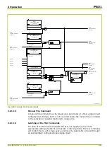
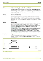
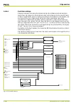
The monitoring signals are also signaled via the output relay configured
SFMON: Warning (relay). The output relay operates as long as an internal
fault is detected.
Q6Z0154A
SFMON:
Warning (LED)
[ 036 070 ]
SFMON:
Hardware fault
304 950
SFMON:
Warning (relay)
[ 036 100 ]
Signal 1
Signal 2
Signal 3
Signal n
m out of n
Selected monit. sig.
SFMON:
Fct. assign. warning
[ 021 030 ]
Fig. 3-63: Monitoring signals.
3 Operation
P631
P631/EN M/R-11-C // P631-310-650
3-91
Summary of Contents for P631
Page 2: ......
Page 4: ......
Page 7: ...Changes after going to press...
Page 8: ......
Page 16: ...P631 Table of Contents 8 P631 EN M R 11 C P631 310 650...
Page 56: ...P631 2 Technical Data 2 28 P631 EN M R 11 C P631 310 650...
Page 236: ...P631 3 Operation 3 180 P631 EN M R 11 C P631 310 650...
Page 246: ...P631 4 Design 4 10 P631 EN M R 11 C P631 310 650...
Page 266: ...P631 5 Installation and Connection 5 20 P631 EN M R 11 C P631 310 650...
Page 276: ...6 8 Configurable Function Keys P631 6 Local Control HMI 6 10 P631 EN M R 11 C P631 310 650...
Page 548: ...P631 10 Commissioning 10 10 P631 EN M R 11 C P631 310 650...
Page 568: ...P631 12 Maintenance 12 8 P631 EN M R 11 C P631 310 650...
Page 570: ...P631 13 Storage 13 2 P631 EN M R 11 C P631 310 650...
Page 572: ...P631 14 Accessories and Spare Parts 14 2 P631 EN M R 11 C P631 310 650...
Page 576: ...P631 15 Order Information 15 4 P631 EN M R 11 C P631 310 650...
Page 582: ...P631 A2 Internal Signals A2 4 P631 EN M R 11 C P631 310 650...
Page 608: ...P631 A4 Telecontrol Interfaces A4 18 P631 EN M R 11 C P631 310 650...
Page 637: ......


