Θ
/ %
t / min
I / I
D5Z50BEB_EN
τ
/ min
1000
30
1
0
1
2
3
4
5
6
7
8
9
10
11
0.01
0.1
1
10
100
1000
10000
0.001
200
110
50
200
110
50
200
110
50
ref
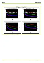
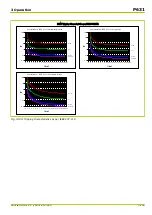
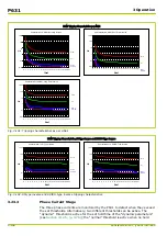
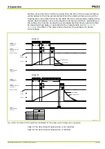
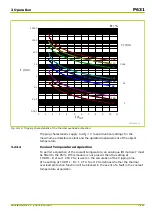
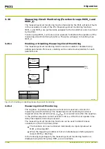
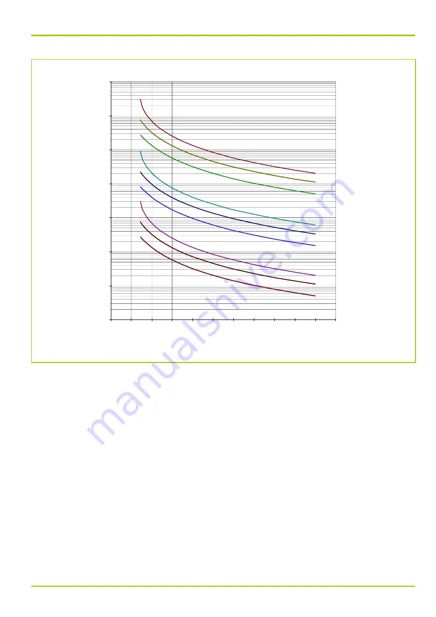
Fig. 3-112: Tripping characteristic of the thermal overload protection.
Tripping characteristics apply to
Δϑ
0
= 0 % and identical settings for the
maximum permissible coolant and the updated measurement of the object
temperature.
3.24.4
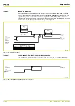
Coolant Temperature Acquisition
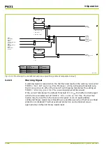
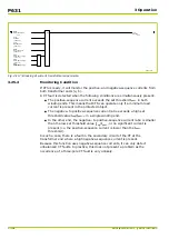
To permit acquisition of the coolant temperature, an analogue I/O module Y must
be fitted to the P631. If this module is not present then the setting at
THRM1: Default CTA PSx is used in the calculation of the tripping time.
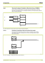
pThe setting at THRM1: Bl. f. CTA fault PSx defines whether the thermal
overload protection function will be blocked in the event of a fault in the coolant
temperature acquisition.
3 Operation
P631
P631/EN M/R-11-C // P631-310-650
3-147
Summary of Contents for P631
Page 2: ......
Page 4: ......
Page 7: ...Changes after going to press...
Page 8: ......
Page 16: ...P631 Table of Contents 8 P631 EN M R 11 C P631 310 650...
Page 56: ...P631 2 Technical Data 2 28 P631 EN M R 11 C P631 310 650...
Page 236: ...P631 3 Operation 3 180 P631 EN M R 11 C P631 310 650...
Page 246: ...P631 4 Design 4 10 P631 EN M R 11 C P631 310 650...
Page 266: ...P631 5 Installation and Connection 5 20 P631 EN M R 11 C P631 310 650...
Page 276: ...6 8 Configurable Function Keys P631 6 Local Control HMI 6 10 P631 EN M R 11 C P631 310 650...
Page 548: ...P631 10 Commissioning 10 10 P631 EN M R 11 C P631 310 650...
Page 568: ...P631 12 Maintenance 12 8 P631 EN M R 11 C P631 310 650...
Page 570: ...P631 13 Storage 13 2 P631 EN M R 11 C P631 310 650...
Page 572: ...P631 14 Accessories and Spare Parts 14 2 P631 EN M R 11 C P631 310 650...
Page 576: ...P631 15 Order Information 15 4 P631 EN M R 11 C P631 310 650...
Page 582: ...P631 A2 Internal Signals A2 4 P631 EN M R 11 C P631 310 650...
Page 608: ...P631 A4 Telecontrol Interfaces A4 18 P631 EN M R 11 C P631 310 650...
Page 637: ......


