6.10
Control at Panel Level
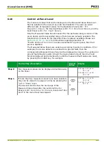
The measured values that will be displayed on the Measured Value Panels can
first be selected in the menu tree under
Par/Conf/LOC
. The user can select
different sets of measured values for the Operation Panel (LOC: Fct.
Operation Panel), the Overload Panel (LOC: Fct. Overload Panel), and the
Fault Panel (LOC: Fct. Fault Panel).
Only the Measured Value Panels relevant for the particular design version of the
given device and its associated range of functions are actually available. The
selected set of values for the Operation Panel is always available. Please see
for instructions regarding selection. If
“MAIN: Without function” has been selected for a given panel, then that
panel is disabled.
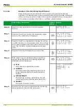
The Measured Value Panels are called up according to system conditions. If, for
example, the device detects an overload or a ground fault, then the
corresponding Measured Value Panel will be displayed as long as the overload or
ground fault situation exists. Should the device detect a fault, then the Fault
Panel is displayed and remains active until the measured fault values are reset,
by pressing the CLEAR key, for example.
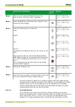
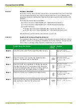
Control Step / Description
Control
Action
Display
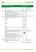
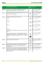
Step 0
Two measured values can be displayed simultaneously
on the Panel.
Voltage A-B prim.
20.7 kV
Voltage B-C prim.
20.6 kV
Step 1
If more than two measured values have been selected,
they can be viewed one page at a time by pressing the
“up” or “down” keys.
The device will also show the next page of the
Measured Value Panel after the set Hold-Time for
Panels (LOC: Hold-time for Panels, located at “
Par/
Conf
” in the menu tree) has elapsed.
or
Voltage C-A prim.
20.8 kV
Current A prim.
415 A
6 Local Control (HMI)
P631
P631/EN M/R-11-C // P631-310-650
6-15
Summary of Contents for P631
Page 2: ......
Page 4: ......
Page 7: ...Changes after going to press...
Page 8: ......
Page 16: ...P631 Table of Contents 8 P631 EN M R 11 C P631 310 650...
Page 56: ...P631 2 Technical Data 2 28 P631 EN M R 11 C P631 310 650...
Page 236: ...P631 3 Operation 3 180 P631 EN M R 11 C P631 310 650...
Page 246: ...P631 4 Design 4 10 P631 EN M R 11 C P631 310 650...
Page 266: ...P631 5 Installation and Connection 5 20 P631 EN M R 11 C P631 310 650...
Page 276: ...6 8 Configurable Function Keys P631 6 Local Control HMI 6 10 P631 EN M R 11 C P631 310 650...
Page 548: ...P631 10 Commissioning 10 10 P631 EN M R 11 C P631 310 650...
Page 568: ...P631 12 Maintenance 12 8 P631 EN M R 11 C P631 310 650...
Page 570: ...P631 13 Storage 13 2 P631 EN M R 11 C P631 310 650...
Page 572: ...P631 14 Accessories and Spare Parts 14 2 P631 EN M R 11 C P631 310 650...
Page 576: ...P631 15 Order Information 15 4 P631 EN M R 11 C P631 310 650...
Page 582: ...P631 A2 Internal Signals A2 4 P631 EN M R 11 C P631 310 650...
Page 608: ...P631 A4 Telecontrol Interfaces A4 18 P631 EN M R 11 C P631 310 650...
Page 637: ......

