Parameter
Address
Default
Min
Max
Unit
Logic Diagram
[spacer]
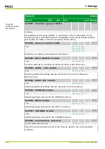
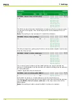
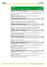
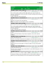
COMM1: Delta t
003 053
1
0
15
min
Fig. 3-7, (p. 3-12)
Fig. 3-8, (p. 3-13)
Fig. 3-9, (p. 3-14)
[spacer]
All measured values are transmitted again via the communication interface after
this time period has elapsed – provided that transmission has not been triggered
by the other delta conditions.
Note: This setting is hidden unless an IEC 870-5 protocol is enabled.
[spacer]
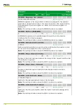
COMM1: Contin. general scan
003 077
Blocked
10
9000
s
Fig. 3-7, (p. 3-12)
Fig. 3-8, (p. 3-13)
Fig. 3-9, (p. 3-14)
[spacer]
A continuous or background general scan means that the P631 transmits all
settings, signals, and monitoring signals through the communication interface
during slow periods when there is not much activity. This ensures that there will
be data consistency with a connected control system. The time to be set defines
the minimum time difference between two telegrams.
Note: This setting is hidden unless an IEC 870-5 protocol is enabled.
[spacer]
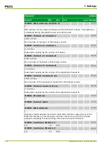
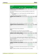
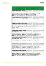
COMM1: Comm. address length
003 201
1
1
2
Byte
[spacer]
Setting for the communication address length.
Note: This setting is hidden unless the IEC 870-5-101 protocol is set.
[spacer]
COMM1: Octet 2 comm. addr.
003 200
0
0
255
[spacer]
Setting for the length of the higher-order communication address.
Note: This setting is hidden unless the IEC 870-5-101 protocol is set.
[spacer]
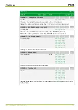
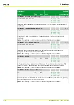
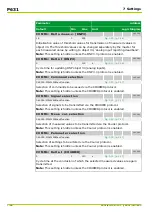
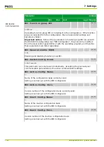
COMM1: Cause transm. length
003 192
1: W/o source address
[spacer]
Setting for the length of the cause of transmission.
Note: This setting is hidden unless the IEC 870-5-101 protocol is set.
[spacer]
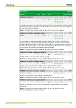
COMM1: Address length ASDU
003 193
1
1
2
Byte
[spacer]
Setting for the length of the common address for identification of telegram
structures.
Note: This setting is hidden unless the IEC 870-5-101 protocol is set.
“ASDU”: Application Service Data Unit
7 Settings
P631
P631/EN M/R-11-C // P631-310-650
7-21
Summary of Contents for P631
Page 2: ......
Page 4: ......
Page 7: ...Changes after going to press...
Page 8: ......
Page 16: ...P631 Table of Contents 8 P631 EN M R 11 C P631 310 650...
Page 56: ...P631 2 Technical Data 2 28 P631 EN M R 11 C P631 310 650...
Page 236: ...P631 3 Operation 3 180 P631 EN M R 11 C P631 310 650...
Page 246: ...P631 4 Design 4 10 P631 EN M R 11 C P631 310 650...
Page 266: ...P631 5 Installation and Connection 5 20 P631 EN M R 11 C P631 310 650...
Page 276: ...6 8 Configurable Function Keys P631 6 Local Control HMI 6 10 P631 EN M R 11 C P631 310 650...
Page 548: ...P631 10 Commissioning 10 10 P631 EN M R 11 C P631 310 650...
Page 568: ...P631 12 Maintenance 12 8 P631 EN M R 11 C P631 310 650...
Page 570: ...P631 13 Storage 13 2 P631 EN M R 11 C P631 310 650...
Page 572: ...P631 14 Accessories and Spare Parts 14 2 P631 EN M R 11 C P631 310 650...
Page 576: ...P631 15 Order Information 15 4 P631 EN M R 11 C P631 310 650...
Page 582: ...P631 A2 Internal Signals A2 4 P631 EN M R 11 C P631 310 650...
Page 608: ...P631 A4 Telecontrol Interfaces A4 18 P631 EN M R 11 C P631 310 650...
Page 637: ......

