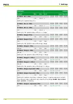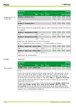
Parameter
Address
Default
Min
Max
Unit
Logic Diagram
[spacer]
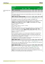
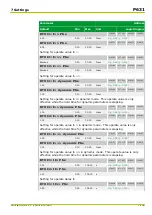
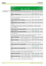
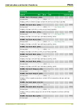
IDMT1: Iref,P dynamic PSx
081 052
082 052
083 052
084 052
1.00
0.10
4.00
Inom
[spacer]
IDMT2: Iref,P dynamic PSx
081 172
082 172
083 172
084 172
1.00
0.10
4.00
Inom
[spacer]
Setting for the reference current (phase current system) in dynamic mode. This
operate value is only effective while the hold time for dynamic parameters is
elapsing.
[spacer]
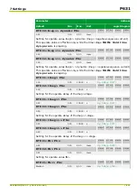
IDMT1: Characteristic P PSx
081 053
082 053
083 053
084 053
0: Definite Time
[spacer]
IDMT2: Characteristic P PSx
081 173
082 173
083 173
084 173
0: Definite Time
[spacer]
Setting for the tripping characteristic (phase current system).
[spacer]
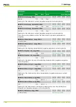
IDMT1: Factor kt,P PSx
081 054
082 054
083 054
084 054
1.00
0.05
10.00
[spacer]
IDMT2: Factor kt,P PSx
081 174
082 174
083 174
084 174
1.00
0.05
10.00
[spacer]
Setting for the factor kt,P of the starting characteristic (phase current system).
[spacer]
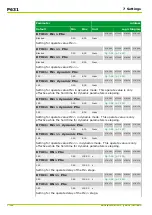
IDMT1: Min. trip t. P PSx
081 057
082 057
083 057
084 057
1.00
0.00
10.00
s
[spacer]
IDMT2: Min. trip t. P PSx
081 177
082 177
083 177
084 177
1.00
0.00
10.00
s
[spacer]
Setting for the minimum trip time (phase current system).
[spacer]
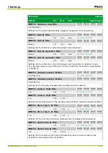
IDMT1: Hold time P PSx
081 055
082 055
083 055
084 055
0.00
0.00
600.00
s
[spacer]
IDMT2: Hold time P PSx
081 175
082 175
083 175
084 175
0.00
0.00
600.00
s
[spacer]
Setting for the hold time for storing the starting time once the starting has
dropped out (phase current system).
[spacer]
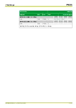
IDMT1: Release P PSx
081 056
082 056
083 056
084 056
1: Without delay
[spacer]
IDMT2: Release P PSx
081 176
082 176
083 176
084 176
1: Without delay
[spacer]
Setting for the reset characteristic (phase current system).
[spacer]
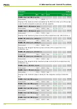
IDMT1: Iref,neg PSx
081 111
082 111
083 111
084 111
Blocked
0.01
0.80
Inom
7 Settings
P631
P631/EN M/R-11-C // P631-310-650
7-115
Summary of Contents for P631
Page 2: ......
Page 4: ......
Page 7: ...Changes after going to press...
Page 8: ......
Page 16: ...P631 Table of Contents 8 P631 EN M R 11 C P631 310 650...
Page 56: ...P631 2 Technical Data 2 28 P631 EN M R 11 C P631 310 650...
Page 236: ...P631 3 Operation 3 180 P631 EN M R 11 C P631 310 650...
Page 246: ...P631 4 Design 4 10 P631 EN M R 11 C P631 310 650...
Page 266: ...P631 5 Installation and Connection 5 20 P631 EN M R 11 C P631 310 650...
Page 276: ...6 8 Configurable Function Keys P631 6 Local Control HMI 6 10 P631 EN M R 11 C P631 310 650...
Page 548: ...P631 10 Commissioning 10 10 P631 EN M R 11 C P631 310 650...
Page 568: ...P631 12 Maintenance 12 8 P631 EN M R 11 C P631 310 650...
Page 570: ...P631 13 Storage 13 2 P631 EN M R 11 C P631 310 650...
Page 572: ...P631 14 Accessories and Spare Parts 14 2 P631 EN M R 11 C P631 310 650...
Page 576: ...P631 15 Order Information 15 4 P631 EN M R 11 C P631 310 650...
Page 582: ...P631 A2 Internal Signals A2 4 P631 EN M R 11 C P631 310 650...
Page 608: ...P631 A4 Telecontrol Interfaces A4 18 P631 EN M R 11 C P631 310 650...
Page 637: ......

