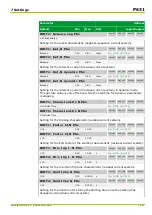
Parameter
Address
Default
Min
Max
Unit
Logic Diagram
Measuring-circuit
monitoring
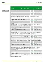
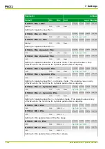
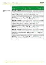
MCM_1: Enable PSx
081 038
082 038
083 038
084 038
0: No
[spacer]
MCM_2: Enable PSx
081 039
082 039
083 039
084 039
0: No
[spacer]
This setting defines the parameter subset in which measuring-circuit monitoring
is enabled.
[spacer]
MCM_1: Ineg/Ipos> PSx
081 042
082 042
083 042
084 042
0.30
0.20
1.00
[spacer]
MCM_2: Ineg/Ipos> PSx
081 043
082 043
083 043
084 043
0.30
0.20
1.00
[spacer]
Setting for the operate value for the ratio I
neg
/I
pos
.
(I
neg
= negative-sequence current, I
pos
= positive-sequence current)
[spacer]
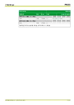
MCM_1: Operate delay PSx
081 046
082 046
083 046
084 046
5.00
0.10
100.00
s
[spacer]
MCM_2: Operate delay PSx
081 047
082 047
083 047
084 047
5.00
0.10
100.00
s
[spacer]
Setting for the operate delay.
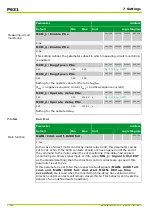
7.1.3.4
Control
Parameter
Address
Default
Min
Max
Unit
Logic Diagram
Main function
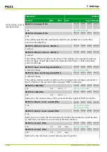
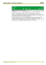
MAIN: Cmd.end f.K200 fail.
221 111
1: Yes
[spacer]
In the case of direct motor control by motor relay K200, this parameter can be
set to
Yes
or
No
. If the K200 contacts should not have opened until the end of
the command to the motor when the set monitoring time-delay had expired
(monitoring via binary signal input –U 706, signal SIG_1: Signal S012 EXT
as the standard setting) then the direction control contacts are opened if this
parameter is set to
Yes
.
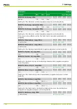
If this parameter is set to
No
then respective fault signals (MAIN: K200 fail.
cmd. end, MAIN: K200 fail. cmd.start, MAIN: DEV op.time
exceeded) are issued when the monitoring time-delay has expired and the
direction control contacts will remain closed. (Note: This behavior still bears the
danger of an undefined switch position!)
P631
7 Settings
7-122
P631/EN M/R-11-C // P631-310-650
Summary of Contents for P631
Page 2: ......
Page 4: ......
Page 7: ...Changes after going to press...
Page 8: ......
Page 16: ...P631 Table of Contents 8 P631 EN M R 11 C P631 310 650...
Page 56: ...P631 2 Technical Data 2 28 P631 EN M R 11 C P631 310 650...
Page 236: ...P631 3 Operation 3 180 P631 EN M R 11 C P631 310 650...
Page 246: ...P631 4 Design 4 10 P631 EN M R 11 C P631 310 650...
Page 266: ...P631 5 Installation and Connection 5 20 P631 EN M R 11 C P631 310 650...
Page 276: ...6 8 Configurable Function Keys P631 6 Local Control HMI 6 10 P631 EN M R 11 C P631 310 650...
Page 548: ...P631 10 Commissioning 10 10 P631 EN M R 11 C P631 310 650...
Page 568: ...P631 12 Maintenance 12 8 P631 EN M R 11 C P631 310 650...
Page 570: ...P631 13 Storage 13 2 P631 EN M R 11 C P631 310 650...
Page 572: ...P631 14 Accessories and Spare Parts 14 2 P631 EN M R 11 C P631 310 650...
Page 576: ...P631 15 Order Information 15 4 P631 EN M R 11 C P631 310 650...
Page 582: ...P631 A2 Internal Signals A2 4 P631 EN M R 11 C P631 310 650...
Page 608: ...P631 A4 Telecontrol Interfaces A4 18 P631 EN M R 11 C P631 310 650...
Page 637: ......

