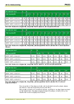
Transformer end
a
b
Vector group ID
0=1
2
1
2
3
4
5
6
7
8
9
10
11
DIFF: Diff. current 1
0.67 0.67 0.58 0.33 0.00 0.33 0.58 0.67 0.58 0.33 0.00 0.33 0.58
DIFF: Diff. current 2
0.33 0.33 0.00 0.33 0.58 0.67 0.58 0.33 0.00 0.33 0.58 0.67 0.58
DIFF: Diff. current 3
0.33 0.33 0.58 0.67 0.58 0.33 0.00 0.33 0.58 0.67 0.58 0.33 0.00
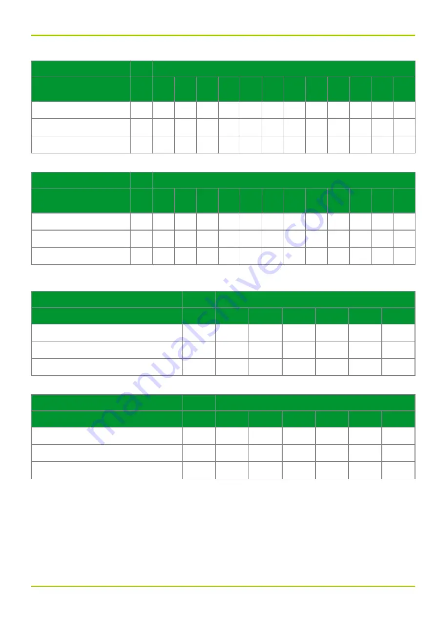
Tab. 10-1: Factors for single-side, one-phase feed in phase A, zero sequence-filtered.
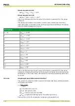
Transformer end
a
b
Vector group ID
0=1
2
1
2
3
4
5
6
7
8
9
10
11
DIFF: Diff. current 1
0.00 0.00 0.58 1.00 1.15 1.00 0.58 0.00 0.58 1.00 1.15 1.00 0.58
DIFF: Diff. current 2
1.00 1.00 1.15 1.00 0.58 0.00 0.58 1.00 1.15 1.00 0.58 0.00 0.58
DIFF: Diff. current 3
1.00 1.00 0.58 0.00 0.58 1.00 1.15 1.00 0.58 0.00 0.58 1.00 1.15
Tab. 10-2: Factors for single-side, two-phase, phase-opposition feed in phases B to C, zero sequence-
filtered.
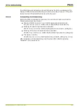
Transformer end
a
b
Vector group ID
0=12
2
4
6
8
10
DIFF: Diff. current 1
1.00
1.00
0.00
0.00
1.00
0.00
0.00
DIFF: Diff. current 2
0.00
0.00
0.00
1.00
0.00
0.00
1.00
DIFF: Diff. current 3
0.00
0.00
1.00
0.00
0.00
1.00
0.00
Tab. 10-3: Factors for single-side, one-phase feed in phase A, not zero sequence-filtered.
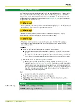
Transformer end
a
b
Vector group ID
0=12
2
4
6
8
10
DIFF: Diff. current 1
0.00
0.00
1.00
1.00
0.00
1.00
1.00
DIFF: Diff. current 2
1.00
1.00
1.00
0.00
1.00
1.00
0.00
DIFF: Diff. current 3
1.00
1.00
0.00
1.00
1.00
0.00
1.00
Tab. 10-4: Factors for single-side, two-phase, phase-opposition feed in phases B to C, not zero
sequence-filtered.
The connection of the phase currents can be checked using the phase angles
provided as measured operating data by the P631.
If the phase currents are connected correctly and there is an ideal balanced load
on the transformer, the phase angles between the phase currents of any one
transformer end are displayed as follows:
10 Commissioning
P631
P631/EN M/R-11-C // P631-310-650
10-7
Summary of Contents for P631
Page 2: ......
Page 4: ......
Page 7: ...Changes after going to press...
Page 8: ......
Page 16: ...P631 Table of Contents 8 P631 EN M R 11 C P631 310 650...
Page 56: ...P631 2 Technical Data 2 28 P631 EN M R 11 C P631 310 650...
Page 236: ...P631 3 Operation 3 180 P631 EN M R 11 C P631 310 650...
Page 246: ...P631 4 Design 4 10 P631 EN M R 11 C P631 310 650...
Page 266: ...P631 5 Installation and Connection 5 20 P631 EN M R 11 C P631 310 650...
Page 276: ...6 8 Configurable Function Keys P631 6 Local Control HMI 6 10 P631 EN M R 11 C P631 310 650...
Page 548: ...P631 10 Commissioning 10 10 P631 EN M R 11 C P631 310 650...
Page 568: ...P631 12 Maintenance 12 8 P631 EN M R 11 C P631 310 650...
Page 570: ...P631 13 Storage 13 2 P631 EN M R 11 C P631 310 650...
Page 572: ...P631 14 Accessories and Spare Parts 14 2 P631 EN M R 11 C P631 310 650...
Page 576: ...P631 15 Order Information 15 4 P631 EN M R 11 C P631 310 650...
Page 582: ...P631 A2 Internal Signals A2 4 P631 EN M R 11 C P631 310 650...
Page 608: ...P631 A4 Telecontrol Interfaces A4 18 P631 EN M R 11 C P631 310 650...
Page 637: ......

