A3
GLOSSARY
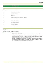
Modules
A:
Communication module
B:
Digital bus module
L:
MMI module
N
Transient ground fault evaluation module
P:
Processor module
T:
Transformer module
V:
Power supply module
X:
Binary I/O module
Y:
Analog I/O module
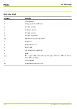
Symbols
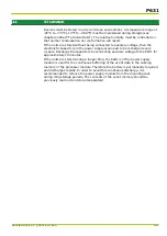
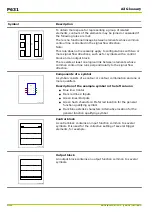
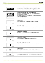
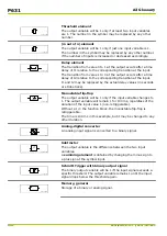
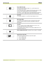
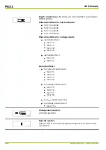
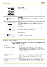
Graphic symbols for block diagrams
Binary elements in compliance with DIN 40900 part 12, September 1992,
IEC 617-12: modified 1991
Analog information processing in compliance with DIN 40900 part 13, January
1981. To document the linking of analog and binary signals, additional symbols
have been used, taken from several DIN documents.
As a rule, direction of the signal flow is from left to right and from top to bottom.
Other flow directions are marked by an arrow. Input signals are listed on the left
side of the signal flow, output signals on the right side.
P631
P631/EN M/R-11-C // P631-310-650
A3-1
Summary of Contents for P631
Page 2: ......
Page 4: ......
Page 7: ...Changes after going to press...
Page 8: ......
Page 16: ...P631 Table of Contents 8 P631 EN M R 11 C P631 310 650...
Page 56: ...P631 2 Technical Data 2 28 P631 EN M R 11 C P631 310 650...
Page 236: ...P631 3 Operation 3 180 P631 EN M R 11 C P631 310 650...
Page 246: ...P631 4 Design 4 10 P631 EN M R 11 C P631 310 650...
Page 266: ...P631 5 Installation and Connection 5 20 P631 EN M R 11 C P631 310 650...
Page 276: ...6 8 Configurable Function Keys P631 6 Local Control HMI 6 10 P631 EN M R 11 C P631 310 650...
Page 548: ...P631 10 Commissioning 10 10 P631 EN M R 11 C P631 310 650...
Page 568: ...P631 12 Maintenance 12 8 P631 EN M R 11 C P631 310 650...
Page 570: ...P631 13 Storage 13 2 P631 EN M R 11 C P631 310 650...
Page 572: ...P631 14 Accessories and Spare Parts 14 2 P631 EN M R 11 C P631 310 650...
Page 576: ...P631 15 Order Information 15 4 P631 EN M R 11 C P631 310 650...
Page 582: ...P631 A2 Internal Signals A2 4 P631 EN M R 11 C P631 310 650...
Page 608: ...P631 A4 Telecontrol Interfaces A4 18 P631 EN M R 11 C P631 310 650...
Page 637: ......

