3.16
Monitoring Signal Recording (Function Group MT_RC)
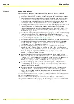
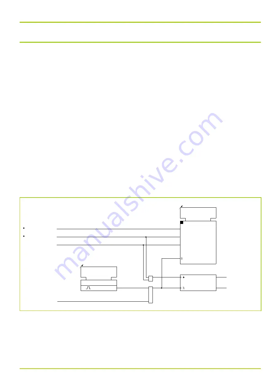
The monitoring signals generated by the self-monitoring function are recorded in
the monitoring signal memory. The memory buffer allows for a maximum of
30 entries. If more than 29 monitoring signals occur without interim memory
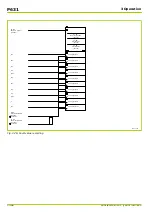
clearance, the SFMON: Overflow MT_RC signal is entered as the last entry.
Monitoring signals prompted by a hardware fault in the unit are always entered
in the monitoring signal memory. Monitoring signals prompted by a peripheral
fault can be entered into the monitoring signal memory, if desired. The user can
select this option by setting an “m out of n” parameter (see
If at least one entry is stored in the monitoring signal memory, this fact is
signaled by the red LED indicator H 3 on the local control panel. Each new entry
causes the LED to flash (on/off/on....).
The monitoring signal memory can only be cleared manually by a control action.
Entries in the monitoring signal memory are not cleared automatically, even if
the corresponding test in a new test cycle now shows the P631 to be healthy.
The contents of the monitoring signal memory can be read from the local control
panel or through the PC or communication interface. The time and date
information assigned to the individual entries can be read out through the PC or
communication interface or from the local control panel.
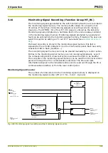
Monitoring Signal Counter
The number of entries stored in the monitoring signal memory is displayed on
the monitoring signal counter (MT_RC: No. monit. signals).
12Z6155A
MT_RC:
Reset record. USER
[ 003 008 ]
0: don't execute
0
1
1: execute
MAIN:
Time tag
306 021
SFMON:
Overflow MT_RC
[ 090 012 ]
SFMON:
Hardware fault
304 950
Selected monit. sig.
MT_RC:
No. monit. signals
[ 004 019 ]
CT30
MT_RC:
Mon. signal record.
[ 003 001 ]
MT_RC:
Reset record. EXT
[ 005 240 ]
≥
1
≥
1
Fig. 3-65: Monitoring signal recording and the monitoring signal counter.
3 Operation
P631
P631/EN M/R-11-C // P631-310-650
3-95
Summary of Contents for P631
Page 2: ......
Page 4: ......
Page 7: ...Changes after going to press...
Page 8: ......
Page 16: ...P631 Table of Contents 8 P631 EN M R 11 C P631 310 650...
Page 56: ...P631 2 Technical Data 2 28 P631 EN M R 11 C P631 310 650...
Page 236: ...P631 3 Operation 3 180 P631 EN M R 11 C P631 310 650...
Page 246: ...P631 4 Design 4 10 P631 EN M R 11 C P631 310 650...
Page 266: ...P631 5 Installation and Connection 5 20 P631 EN M R 11 C P631 310 650...
Page 276: ...6 8 Configurable Function Keys P631 6 Local Control HMI 6 10 P631 EN M R 11 C P631 310 650...
Page 548: ...P631 10 Commissioning 10 10 P631 EN M R 11 C P631 310 650...
Page 568: ...P631 12 Maintenance 12 8 P631 EN M R 11 C P631 310 650...
Page 570: ...P631 13 Storage 13 2 P631 EN M R 11 C P631 310 650...
Page 572: ...P631 14 Accessories and Spare Parts 14 2 P631 EN M R 11 C P631 310 650...
Page 576: ...P631 15 Order Information 15 4 P631 EN M R 11 C P631 310 650...
Page 582: ...P631 A2 Internal Signals A2 4 P631 EN M R 11 C P631 310 650...
Page 608: ...P631 A4 Telecontrol Interfaces A4 18 P631 EN M R 11 C P631 310 650...
Page 637: ......

