3.24.2
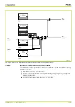
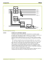
Readiness of Thermal Overload Protection
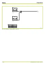
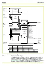
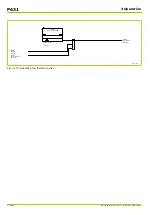
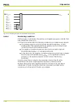
Thermal overload protection will issue the THRM1: Not ready signal if one of
the following conditions applies:
●
Thermal overload protection is disabled.
●
Thermal overload protection is blocked because of a fault in the coolant
temperature (ambient) acquisition.
●
Thermal overload protection is blocked because of an incorrect setting.
●
The thermal replica is blocked via an appropriately configured binary signal
input.
64Z5190A
THRM1:
Not ready
[ 039 154 ]
THRM1:
Enabled
[ 039 129 ]
THRM1:
Replica block EXT
[ 039 150 ]
THRM1:
Setting error,block.
[ 039 126 ]
THRM1:
Block. by CTA error
305 221
Fig. 3-111: THRM1: Not ready
3.24.3
Tripping Characteristics
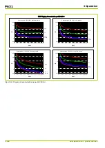
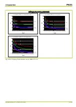
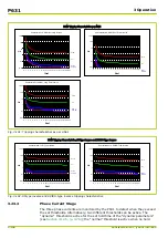
The maximum phase current IP,max.y of the selected transformer end is used to
track a first-order thermal replica according to IEC 255-8. The following
parameters will govern the tripping parameters:
●
The set thermal time constant (
τ
) of the protected object
THRM1: Tim.const.1,>Ibl PSx
●
The tripping threshold
Δϑ
trip
set at THRM1: Rel. O/T trip PSx
●
The accumulated thermal load
Δϑ
0
●
The updated measured coolant temperature
Θ
c
for the protected object
●
The maximum permissible coolant temperature
Θ
c,max
set at
THRM1: Max.perm.cool.tmpPSx
●
The maximum permissible object temperature
Θ
max
set at
THRM1: Max.perm.obj.tmp.PSx
The object temperature is calculated from the current I
P,max.y
and can be
displayed at THRM1: Object temperat.,TH1. The coolant temperature is
either measured via the PT 100 input or via a 20 mA input, or a default
temperature value is used instead. This choice is governed by the setting at
THRM1: Select CTA PSx. The coolant temperature is displayed at
THRM1: Coolant temp. TH1. The difference between the settings for the
maximum permissible temperatures of the protected object and the coolant can
be displayed at THRM1: O/T f.Iref persist 1.
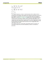
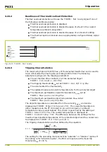
The tripping characteristics are then defined by the equation:
t
=
τ
⋅
ln
(
I
I
ref
)
2
−
Δϑ
0
(
I
I
ref
)
2
−
Δϑ
trip
⋅
(
1
−
Θ
c
−
Θ
c
,max
Θ
max
−
Θ
c
,max
)
The setting for the operating mode selects an “absolute” or “relative” replica. If
the setting is for “Absolute replica”, the P631 will operate with a fixed trip
threshold
Δ
trip
of 100 %.
P631
3 Operation
3-146
P631/EN M/R-11-C // P631-310-650
Summary of Contents for P631
Page 2: ......
Page 4: ......
Page 7: ...Changes after going to press...
Page 8: ......
Page 16: ...P631 Table of Contents 8 P631 EN M R 11 C P631 310 650...
Page 56: ...P631 2 Technical Data 2 28 P631 EN M R 11 C P631 310 650...
Page 236: ...P631 3 Operation 3 180 P631 EN M R 11 C P631 310 650...
Page 246: ...P631 4 Design 4 10 P631 EN M R 11 C P631 310 650...
Page 266: ...P631 5 Installation and Connection 5 20 P631 EN M R 11 C P631 310 650...
Page 276: ...6 8 Configurable Function Keys P631 6 Local Control HMI 6 10 P631 EN M R 11 C P631 310 650...
Page 548: ...P631 10 Commissioning 10 10 P631 EN M R 11 C P631 310 650...
Page 568: ...P631 12 Maintenance 12 8 P631 EN M R 11 C P631 310 650...
Page 570: ...P631 13 Storage 13 2 P631 EN M R 11 C P631 310 650...
Page 572: ...P631 14 Accessories and Spare Parts 14 2 P631 EN M R 11 C P631 310 650...
Page 576: ...P631 15 Order Information 15 4 P631 EN M R 11 C P631 310 650...
Page 582: ...P631 A2 Internal Signals A2 4 P631 EN M R 11 C P631 310 650...
Page 608: ...P631 A4 Telecontrol Interfaces A4 18 P631 EN M R 11 C P631 310 650...
Page 637: ......

