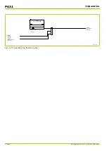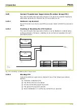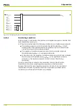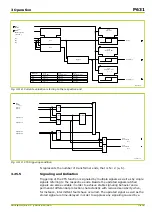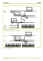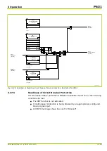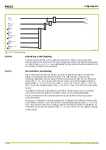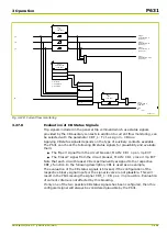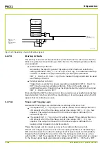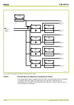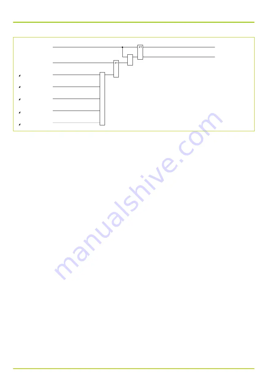
CBF_1:
Enabled
[ 040 055 ]
CBF_1:
Not ready
[ 040 025 ]
CBF_1:
Blocking EXT
[ 038 058 ]
CBF_1:
t2
[ 022 166 ]
CBF_1:
Delay/starting trig.
[ 022 155 ]
CBF_1:
Delay/fault beh. CB
[ 022 171 ]
CBF_1:
Delay/CB sync.superv
[ 022 172 ]
CBF_1:
t1 3p
[ 022 165 ]
64Z1102B
blocked
blocked
blocked
blocked
blocked
&
&
CBF_1:
Ready
[ 038 009 ]
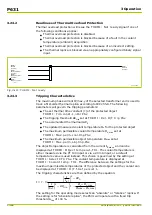
Fig. 3-127: CBF readiness
3.27.6
Detecting a CB Tripping
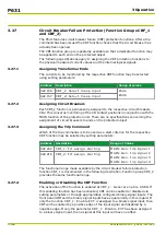
A break in current flow is the preferred criterion to detect a successful CB
tripping. Protection functions that have triggering criteria not directly dependent
on current flow (e.g. V<>), may additionally be provided with status signals from
CB auxiliary contacts for evaluation.
3.27.7
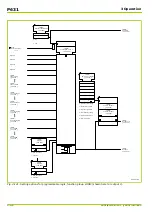
Current flow monitoring
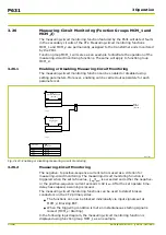
The current flow monitoring function is used to detect a break in current flow
safely, immediately and pole selectively. The CBF function continuously
compares sampled current values from the selected end with the set threshold
value CBF_1: I<. As long as current flow criteria are met the phase-selective
signals CBF_1: Current flow A, CBF_1: Current flow B, CBF_1: Current
flow C and the multiple signal CBF_1: Current flow Phx will be continuously
issued.
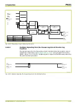
In addition to this line-associated current flow monitoring function a residual
current monitoring function is available which can be enabled/disabled.
For the residual current monitoring the value derived from the three phase
currents is used.
As long as a residual current exceeding the comparator threshold is flowing, the
current flow criterion is not met and the corresponding signal (CBF_1: Current
flow N) is issued. When the residual current monitoring function is disabled, no
monitoring is carried out and the CBF_1: Current flow N = No signal is issued
continuously.
P631
3 Operation
3-160
P631/EN M/R-11-C // P631-310-650
Summary of Contents for P631
Page 2: ......
Page 4: ......
Page 7: ...Changes after going to press...
Page 8: ......
Page 16: ...P631 Table of Contents 8 P631 EN M R 11 C P631 310 650...
Page 56: ...P631 2 Technical Data 2 28 P631 EN M R 11 C P631 310 650...
Page 236: ...P631 3 Operation 3 180 P631 EN M R 11 C P631 310 650...
Page 246: ...P631 4 Design 4 10 P631 EN M R 11 C P631 310 650...
Page 266: ...P631 5 Installation and Connection 5 20 P631 EN M R 11 C P631 310 650...
Page 276: ...6 8 Configurable Function Keys P631 6 Local Control HMI 6 10 P631 EN M R 11 C P631 310 650...
Page 548: ...P631 10 Commissioning 10 10 P631 EN M R 11 C P631 310 650...
Page 568: ...P631 12 Maintenance 12 8 P631 EN M R 11 C P631 310 650...
Page 570: ...P631 13 Storage 13 2 P631 EN M R 11 C P631 310 650...
Page 572: ...P631 14 Accessories and Spare Parts 14 2 P631 EN M R 11 C P631 310 650...
Page 576: ...P631 15 Order Information 15 4 P631 EN M R 11 C P631 310 650...
Page 582: ...P631 A2 Internal Signals A2 4 P631 EN M R 11 C P631 310 650...
Page 608: ...P631 A4 Telecontrol Interfaces A4 18 P631 EN M R 11 C P631 310 650...
Page 637: ......

