64Z1105B
C
t
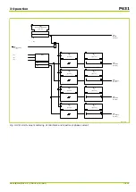
CBF_1:
Not ready
[ 040 025 ]
CBF_1:
Startup 3p
[ 038 211 ]
CBF_1:
Trip signal t1
[ 038 215 ]
CBF_1:
Trip signal t2
[ 038 219 ]
CBF_1:
CB faulty EXT
[ 038 234 ]
CBF_1:
t1 3p
[ 022 165 ]
C
CBF_1:
t2
[ 022 166 ]
MAIN:
CB failure
[ 036 017 ]
&
0
t
0
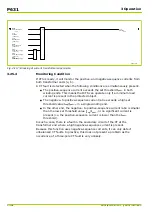
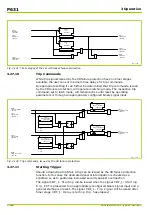
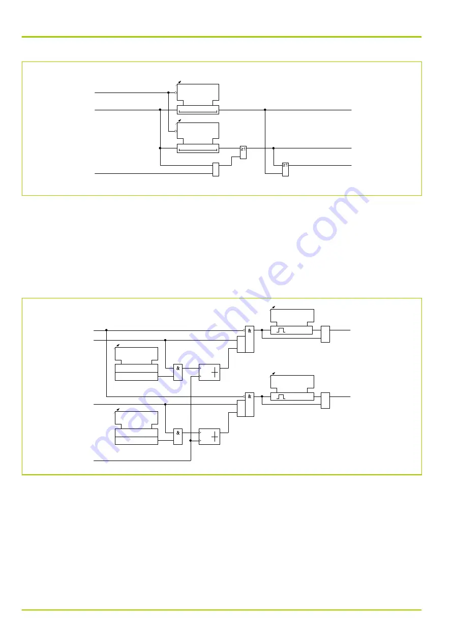
Fig. 3-131: Timer stages of the circuit breaker failure protection
3.27.10
Trip Commands
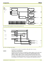
While trip signals issued by the CB failure protection have no timer stages
available the user can set minimum time delays for trip commands.
By appropriate setting it can further be determined that trip commands, issued
by the CB failure protection, will operate in latching mode. The respective trip
command, set to latch mode, will remain active until reset by operating
parameters or through an appropriately configured binary signal input.
CBF_1:
Trip signal t1
[ 038 215 ]
CBF_1:
Trip command t1
[ 038 220 ]
MAIN:
Latch. trip c. reset
[ 040 139 ]
CBF_1:
Min.dur. trip cmd.t1
[ 022 167 ]
1
1
1
S
R
MAIN:
Trip cmd. blocked
[ 021 013 ]
CBF_1:
Latching trip cmd.t1
[ 022 169 ]
0
1
0: No
1: Yes
CBF_1:
Trip signal t2
[ 038 219 ]
CBF_1:
Trip command t2
[ 038 224 ]
t 0
CBF_1:
Min.dur. trip cmd.t2
[ 022 168 ]
1
1
1
S
R
CBF_1:
Latching trip cmd.t2
[ 022 170 ]
0
1
0: No
1: Yes
64Z1106B
≥1
≥1
≥1
≥1
t 0
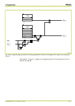
Fig. 3-132: Trip commands, issued by the CB failure protection
3.27.11
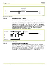
Starting Trigger
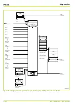
Should a downstream CB fail, a trip can be issued by the CB failure protection
function. In this case the dedicated general interrogation is checked as a
condition so as to guarantee increased security against overreaction.
The signal CBF_1: Starting will be issued when the signal CBF_1: Starting
trig. EXT is presented to an appropriately configured binary signal input and a
general starting is present. The signal CBF_1: Trip signal will be issued after
timer stage CBF_1: Delay/starting trig. has elapsed.
P631
3 Operation
3-164
P631/EN M/R-11-C // P631-310-650
Summary of Contents for P631
Page 2: ......
Page 4: ......
Page 7: ...Changes after going to press...
Page 8: ......
Page 16: ...P631 Table of Contents 8 P631 EN M R 11 C P631 310 650...
Page 56: ...P631 2 Technical Data 2 28 P631 EN M R 11 C P631 310 650...
Page 236: ...P631 3 Operation 3 180 P631 EN M R 11 C P631 310 650...
Page 246: ...P631 4 Design 4 10 P631 EN M R 11 C P631 310 650...
Page 266: ...P631 5 Installation and Connection 5 20 P631 EN M R 11 C P631 310 650...
Page 276: ...6 8 Configurable Function Keys P631 6 Local Control HMI 6 10 P631 EN M R 11 C P631 310 650...
Page 548: ...P631 10 Commissioning 10 10 P631 EN M R 11 C P631 310 650...
Page 568: ...P631 12 Maintenance 12 8 P631 EN M R 11 C P631 310 650...
Page 570: ...P631 13 Storage 13 2 P631 EN M R 11 C P631 310 650...
Page 572: ...P631 14 Accessories and Spare Parts 14 2 P631 EN M R 11 C P631 310 650...
Page 576: ...P631 15 Order Information 15 4 P631 EN M R 11 C P631 310 650...
Page 582: ...P631 A2 Internal Signals A2 4 P631 EN M R 11 C P631 310 650...
Page 608: ...P631 A4 Telecontrol Interfaces A4 18 P631 EN M R 11 C P631 310 650...
Page 637: ......

