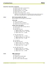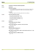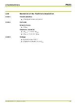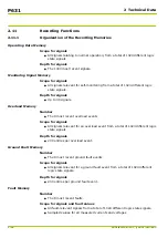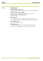
2.6
Interfaces
2.6.1
Local Control Panel
Input or output
●
With 13 keys and a 4 ×20 character liquid crystal display (LCD).
State and fault signals
●
23 LED indicators (5 permanently assigned, 18 freely configurable).
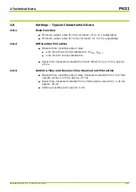
2.6.2
PC Interface
●
Transmission rate: 300 to 115,200 baud (adjustable)
2.6.3
Serial Communication Interface
The communication module can be provided with up to two communication
channels, depending on the module variant. Channel 1 may either be equipped
to connect wire leads or optical fibers and channel 2 is only available to connect
wire leads.
For communication interface 1, communication protocols based on
IEC 870-5
‑
103, IEC 60870
‑
5
‑
101, MODBUS, DNP 3.0, or Courier can be set.
●
Transmission rate: 300 to 64000 baud (adjustable).
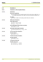
Communication interface 2 can only be operated with the interface protocol
based on IEC 60870-5-103.
●
Transmission rate: 300 or 57600 baud (adjustable).
Wire Leads
●
Per RS 485 or RS 422, 2 kV isolation
●
Distance to be bridged
■
Point-to-point connection: max. 1200 m
■
Multipoint connection: max. 100 m
Plastic Fiber Connection
●
Optical wavelength: typically 660 nm
●
Optical output: min. -7.5 dBm
●
Optical sensitivity: min. -20 dBm
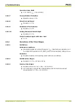
●
Optical input: max. -5 dBm
●
Distance to be bridged: max. 45 m
(Distance to be bridged given for identical optical outputs and inputs at
both ends, a system reserve of 3 dB, and typical fiber attenuation)
Glass Fiber Connection G 50/125
●
Optical wavelength: typically 820 nm
●
Optical output: min. -19.8 dBm
●
Optical sensitivity: min. -24 dBm
●
Optical input: max. -10 dBm
●
Distance to be bridged: max. 400 m
(Distance to be bridged given for identical optical outputs and inputs at
both ends, a system reserve of 3 dB, and typical fiber attenuation)
P631
2 Technical Data
2-14
P631/EN M/R-11-C // P631-310-650
Summary of Contents for P631
Page 2: ......
Page 4: ......
Page 7: ...Changes after going to press...
Page 8: ......
Page 16: ...P631 Table of Contents 8 P631 EN M R 11 C P631 310 650...
Page 56: ...P631 2 Technical Data 2 28 P631 EN M R 11 C P631 310 650...
Page 236: ...P631 3 Operation 3 180 P631 EN M R 11 C P631 310 650...
Page 246: ...P631 4 Design 4 10 P631 EN M R 11 C P631 310 650...
Page 266: ...P631 5 Installation and Connection 5 20 P631 EN M R 11 C P631 310 650...
Page 276: ...6 8 Configurable Function Keys P631 6 Local Control HMI 6 10 P631 EN M R 11 C P631 310 650...
Page 548: ...P631 10 Commissioning 10 10 P631 EN M R 11 C P631 310 650...
Page 568: ...P631 12 Maintenance 12 8 P631 EN M R 11 C P631 310 650...
Page 570: ...P631 13 Storage 13 2 P631 EN M R 11 C P631 310 650...
Page 572: ...P631 14 Accessories and Spare Parts 14 2 P631 EN M R 11 C P631 310 650...
Page 576: ...P631 15 Order Information 15 4 P631 EN M R 11 C P631 310 650...
Page 582: ...P631 A2 Internal Signals A2 4 P631 EN M R 11 C P631 310 650...
Page 608: ...P631 A4 Telecontrol Interfaces A4 18 P631 EN M R 11 C P631 310 650...
Page 637: ......


