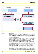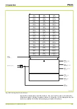
Q9Z5029A
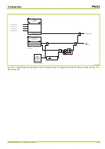
MEASI:
Scaled value IDC,lin
[ 004 180 ]
MEASI:
Scaled val. IDC,lin1
[ 037 192 ]
MEASI:
Curr. IDC,lin. p.u.
[ 004 136 ]
MEASI:
Scaled val.IDC,lin20
[ 037 193 ]
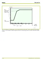
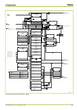
Fig. 3-27: Scaling of the linearized measured value.
3.8.1.1
Zero Suppression
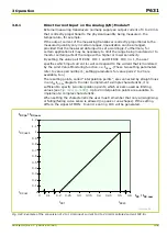
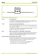
Zero suppression is defined by setting MEASI: Enable IDC p.u. If the direct
current does not exceed the set threshold, the per-unit input current I
DC p.u.
and
the current I
DC,lin
will be displayed as having a value of “
0
”.
3.8.1.2
Open-Circuit and Overload Monitoring
The P631 is equipped with an open-circuit monitoring function. If current I
DC
falls
below the set threshold MEASI: IDC< open circuit, the signal MEASI: Open
circ. 20mA inp. is issued.
The input current is monitored in order to protect the 20 mA analog input against
overloading. If it exceeds the set threshold of 24.8 mA, the signal
MEASI: Overload 20mA input is issued.
3.8.2
Input for Connection of a Resistance Thermometer
This input is designed to connect a PT 100 resistance thermometer. The mapping
curve, R = f(T), of PT 100 resistance thermometers is defined in the IEC 751
standard. If the PT 100 resistance thermometer is connected using the 3-wire
method, then no further calibration is required.
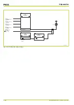
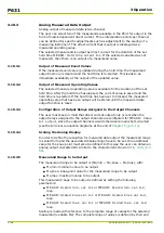
Maximum Temperature Value Since the Last Reset
The result of a temperature measurement cannot only be read out as a direct
measured value (temperature T) or as a normalized value (temperature norm. T),
but also as the maximum value since the last reset (temperature Tmax).
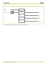
For this the following menu points are available:
●
MEASI: Temperature Tmax (maximum temperature value)
●
MEASI: Reset Tmax EXT (reset via a binary signal)
●
MEASI: Reset Tmax USER (manual reset)
P631
3 Operation
3-42
P631/EN M/R-11-C // P631-310-650
Summary of Contents for P631
Page 2: ......
Page 4: ......
Page 7: ...Changes after going to press...
Page 8: ......
Page 16: ...P631 Table of Contents 8 P631 EN M R 11 C P631 310 650...
Page 56: ...P631 2 Technical Data 2 28 P631 EN M R 11 C P631 310 650...
Page 236: ...P631 3 Operation 3 180 P631 EN M R 11 C P631 310 650...
Page 246: ...P631 4 Design 4 10 P631 EN M R 11 C P631 310 650...
Page 266: ...P631 5 Installation and Connection 5 20 P631 EN M R 11 C P631 310 650...
Page 276: ...6 8 Configurable Function Keys P631 6 Local Control HMI 6 10 P631 EN M R 11 C P631 310 650...
Page 548: ...P631 10 Commissioning 10 10 P631 EN M R 11 C P631 310 650...
Page 568: ...P631 12 Maintenance 12 8 P631 EN M R 11 C P631 310 650...
Page 570: ...P631 13 Storage 13 2 P631 EN M R 11 C P631 310 650...
Page 572: ...P631 14 Accessories and Spare Parts 14 2 P631 EN M R 11 C P631 310 650...
Page 576: ...P631 15 Order Information 15 4 P631 EN M R 11 C P631 310 650...
Page 582: ...P631 A2 Internal Signals A2 4 P631 EN M R 11 C P631 310 650...
Page 608: ...P631 A4 Telecontrol Interfaces A4 18 P631 EN M R 11 C P631 310 650...
Page 637: ......

