MICOM SWING SW & SWSP
Installation Manual
Page
37
9.14
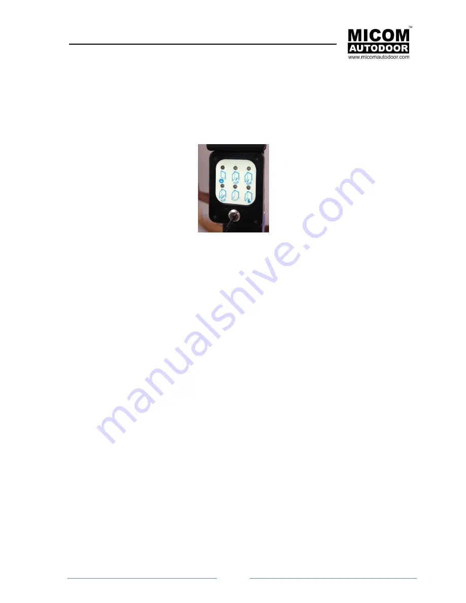
P11 connector: Selector B (Digital)
The P11 connector connects a Digital Selector. In order to change the function mode of the automatic
door and keep it in its memory.
The connection is by a 4- wire cable. Please be careful in the connection because these cable hasve
polarity.
Note: Bridge P7 of the control unit must be connected (it already comes connected from the factory).
Digital Selector B
The voltage used is 5V.
Multiple selectors B (Digital) can be connected to the same Control Unit.
When this selector is connected to the Control Unit, Selector A (three position selector) becomes
deactivated and stops working.
If multiple Selector B (Digital) are required, the following configuration of Selector B is necessary:
1.- Open the cover to access to the electronic board. For this you will have to remove 4
internal screws.
2.- Once the screws have been removed, remove a
“Bridge” called P5.
3.- This procedure should be carried out on all the selectors connected to the operator
EXCEPT in one of them. This should be the one furthest away from the operator. If, for
example, we have an operator with three connected sel
ectors, we should remove the “bridge”
to the two selectors nearest to the operator; the selector which is the furthest away, will not be
modified.
NOTICE! Selector B (Digital) must be connected to the correct Connector. If connected to
wrong connector (for example, sensor or security sensor), it will be irreversibly damaged and
could also damage the Control Unit.


