


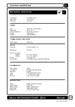

Micon M1500-600/150kW 50Hz
Manual
UK1500.PM6
Rev. 95-06-23 OKK
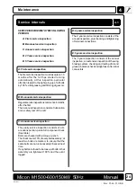
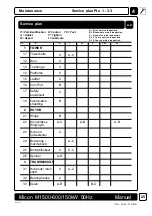
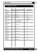
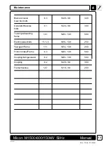
Maintenance
4
Lubricants
4.3
31
ITEM
LUBROCANT
AMOUNT
INTERVAL
NOTES
Hydr. aggre.
(Wingbrakes)
Centrif. sensors
Main bearing
Gearbox
Hydr.oil
(Diskbrakes)
Generator
bearings
Yaw collar
Tooth rim
Yaw gear
(except grease
test)
Yaw brakes
Hinges cowling
Shock abs. ball
joint
Closures
bearings-
doors/Wings
Mobil AERO HFE
Molycote Never
Seez 033916
Mobilith SHC 460
Tribol 1510/320
Hydro TL 15
Mobiltemp
SHC 100
Mobilux 2/
Mobilith 460
Gear wheel fat
Mobilith SHC 460
Mobilith SHC 460
ca. 1.6 litres
100 gr.
80/85 litres
40 gr.
1200 gr.
2 years
(chge 5 yrs)
5 years
6 mnths.
1 year
2 years.
(chge 5 yrs)
6 mnths.
6 mnths.
6 mnths.
1 mnth.
(5 years)
1 year.
1 year.
1 year.
6 mnths.
See LM
manual
Test/change
Test/change
See lubric.
procedure
See pts.11.2
and 11.7
See pt. 12.6
See pt. 14.3
See pt. 14.4