5
FRP MICRO
AIR
®
CLEAN
AIR
SYSTEMS
INSTALLATION:
INSPECTION:
The Micro Air dust collector is shipped on one or more
skids. All skids should be inspected for any visible damage
that may have occurred during shipment.
Report any damage to the delivery carrier.
CODES:
Codes may regulate recirculating fi ltered air in your facility.
Consult with the appropriate authorities having jurisdiction
to ensure compliance with all national and local codes
regarding recirculating of fi ltered air.
Codes may regulate acceptable locations for installing dust
collectors. Consult with the appropriate authorities having
jurisdiction to ensure compliance with all national and local
codes regarding dust collector installation.
Collectors must be anchored in a manner consistent with
local code requirements. Anchors must be suffi cient to
support dead, live, seismic, and other anticipated loads.
SUGGESTED EQUIPMENT & TOOLS:
Crane or Lift truck
Clevis Pins and Clamps
Lifting Straps or Chain
Drift Pins
Spreader
Bars
Pipe
Sealant
Socket Wrenches
Screwdrivers
Pipe Wrenches
Drill and Drill Bits
1/2” diameter anchor bolts
End Wrenches
Adjustable Wrench
Level
SET-UP
1. Determine the location where the unit is to be installed.
Be sure to allow suffi cient room to access the unit for
servicing and maintenance on all sides.
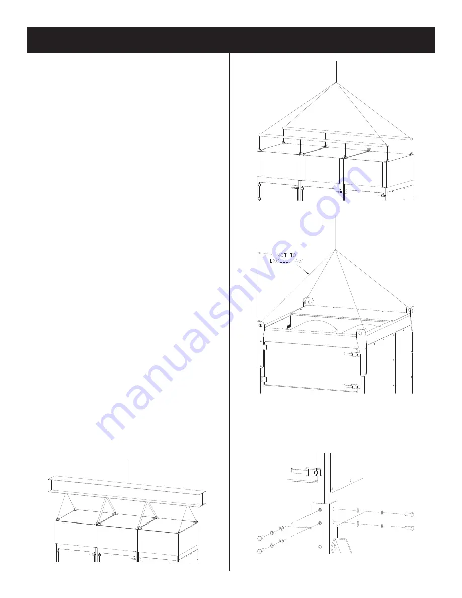
2. Lift the unit with a lift truck or overhead crane rated to
support the dust collectors weight. Use all the lifting
lugs provided and lift in a method described in Figure
1, 2 or 3.
3. Bolt on each of the legs with the hardware provided
(Figure 4).
FIGURE 1
FIGURE 2
FIGURE 3
FIGURE 4
Summary of Contents for FORCE FRP4
Page 13: ...FRP MICRO AIR CLEAN AIR SYSTEMS 13 FRP4 PULSE CONTROL ONLY WIRING DIAGRAM ...
Page 14: ...14 MICRO AIR FRP CLEAN AIR SYSTEMS FRP6 PULSE CONTROL ONLY WIRING DIAGRAM ...
Page 15: ...15 FRP MICRO AIR CLEAN AIR SYSTEMS FRP8 PULSE CONTROL ONLY WIRING DIAGRAM ...
Page 16: ...16 MICRO AIR FRP CLEAN AIR SYSTEMS FRP6 2 PULSE CONTROL ONLY WIRING DIAGRAM ...
Page 17: ...17 FRP MICRO AIR CLEAN AIR SYSTEMS FRP6 3 PULSE CONTROL ONLY WIRING DIAGRAM ...
Page 18: ...18 MICRO AIR FRP CLEAN AIR SYSTEMS FRP8 2 PULSE CONTROL ONLY WIRING DIAGRAM ...
Page 19: ...19 FRP MICRO AIR CLEAN AIR SYSTEMS FRP8 3 PULSE CONTROL ONLY WIRING DIAGRAM ...
Page 20: ...20 MICRO AIR FRP CLEAN AIR SYSTEMS FRP8 4 PULSE CONTROL ONLY WIRING DIAGRAM ...
Page 21: ...21 FRP MICRO AIR CLEAN AIR SYSTEMS FRP4 FULL CONTROL WIRING DIAGRAM ...
Page 22: ...22 MICRO AIR FRP CLEAN AIR SYSTEMS FRP6 FULL CONTROL WIRING DIAGRAM ...
Page 23: ...23 FRP MICRO AIR CLEAN AIR SYSTEMS FRP8 FULL CONTROL WIRING DIAGRAM ...
Page 24: ...24 MICRO AIR FRP CLEAN AIR SYSTEMS FRP6 2 FULL CONTROL WIRING DIAGRAM ...
Page 25: ...25 FRP MICRO AIR CLEAN AIR SYSTEMS FRP6 3 FULL CONTROL WIRING DIAGRAM ...
Page 26: ...26 MICRO AIR FRP CLEAN AIR SYSTEMS FRP8 2 FULL CONTROL WIRING DIAGRAM ...
Page 27: ...27 FRP MICRO AIR CLEAN AIR SYSTEMS FRP8 3 FULL CONTROL WIRING DIAGRAM ...
Page 28: ...28 MICRO AIR FRP CLEAN AIR SYSTEMS FRP8 4 FULL CONTROL WIRING DIAGRAM ...
Page 32: ...32 MICRO AIR FRP CLEAN AIR SYSTEMS THIS PAGE INTENTIONALLY LEFT BLANK ...


