4
MAE2200
®
OPERATION:
CAUTION: ALWAYS MAKE SURE THAT ARM ASSEMBLY
IS FREE FROM OBSTRUCTIONS WHEN LIFTING OR
LOWERING MOTORIZED ARM.
1.
For motorized arm systems, the upper arm section can
be raised and lowered by depressing the toggle switch,
located on top of the remote switch control box, located
near the hood. The linear actuator has limit switches that
override the toggle switch when the arm exceeds the
retracted or extended length of the actuator.
2.
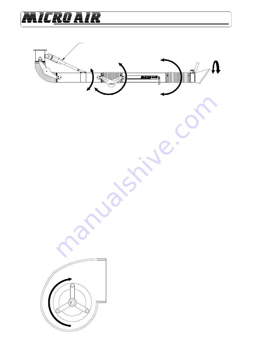
Grasp the nozzle handle and lift the lower arm section up
and down. If the middle joint seems too tight, loosen the
two wing nuts that hold the joint together. If the arm has
trouble maintaining a position, hand tighten the wing nuts.
3.
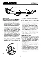
The nozzle-joint section can be manipulated up, down and
rotated. The joints are located inside the flexible hose
nearest the nozzle. If the joints are too loose or tight,
simply remove the hose clamp at the nozzle, gaining
access to the joints, and adjust as needed. (See
FIG. 6
.)
4.
To operate blower, depress the fan switch located on the
remote switch control box to ON. The blower motor will
activate via a motor relay located inside the electrical
control box.
5.
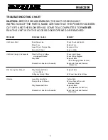
Be sure to check for proper blower rotation. If blower is
rotating backwards, interchange L1 and L2. (See
FIG. 7
.)
6.
Activate the lamp located inside the nozzle by depressing
the lamp switch located on the remote switch control box.
ACTUATOR (OR RIGID PIPE)
90° UP
45° UP
20° UP
90° DOWN
45° DOWN
20° DOWN
7.
The damper lever near the nozzle can be rotated 90° to
adjust inlet air velocity.
PRESSURE SWITCH ADJUSTMENTS
1.
Make sure filters and pre-filters are installed in unit.
2.
The pressure switch is preset at the factory to indicate
(light on) dirty filters, but may need readjustment due to a
desire for earlier or later filter changes, a different
combination of filters, or because the set point shifted
during shipping. To readjust the switch, remove the hole
plug in the side of the unit for access to the adjustment
screw. Turn the unit on and place a piece of cardboard
over the hood covering about 80-85% of the intake. With
a standard screwdriver, turn the adjustment screw
clockwise until the light goes off, or
counterclockwise until the light comes on.
3.
For more time between filter changes (less airflow), cover
slightly more of the hood, and for less time between filter
changes (more airflow), cover less of the hood.
CHANGING FILTERS
CAUTION: ALWAYS MAKE SURE THAT THE UNIT IS TURNED
OFF BEFORE CHANGING FILTERS OR SERVICING THE UNIT.
1. The MAE 2200 is equipped with a filter change light, which
indicates when a filter needs to be replaced. If the differential
pressure has been set properly, the light signals the need for
examination of the filters.
2. When the light comes on, turn the unit off and remove the
pre-filter only. Replace with a new pre-filter, making sure that
the air flow directional arrow is pointed toward the outlet end.
Turn the unit back on. If the filter change light is off, then the
unit is operating properly.
3. If the filter change light fails to go out after replacing the pre-
filter, then the media bag filter may also need to be replaced.
4. Visually inspect the bag filter. If the pockets are loaded with
dirt, then remove the filter from the channel and insert a new
filter.
5. Start the unit. The filter change light should be off and the unit
operating properly.
FIG. 7

