MODELS MT 1251 / 1252
SPECIFICATIONS
Input Volts, 120 Volts, 60Hz
220 Volts, 50/60 Hz.
Max. Current:
Draw-120 V. 6.5 amps (High)
4.0 amps (Low)
230 V. 3.3 amps (High)
2.0 amps (Low)
Dimensions: 14” h. x 24 1/2” w. x 32 3/4” l.
Shipping Wt.: 130lbs.
Actual Wt.: 120 lbs.
PRE-OPERATING INSTRUCTIONS
1.
Upon receipt, remove the unit from carton(s). Remove
plastic wrap. Inspect the unit for any freight damage that may
have occured during shipping. Report any damage to
the freight company.
2.
To gain access to filters, turn captive screw latch on filter
access covers counter-clockwise until cover can be pulled free
from cabinet. Remove covers from cabinet.
3.
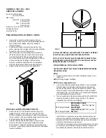
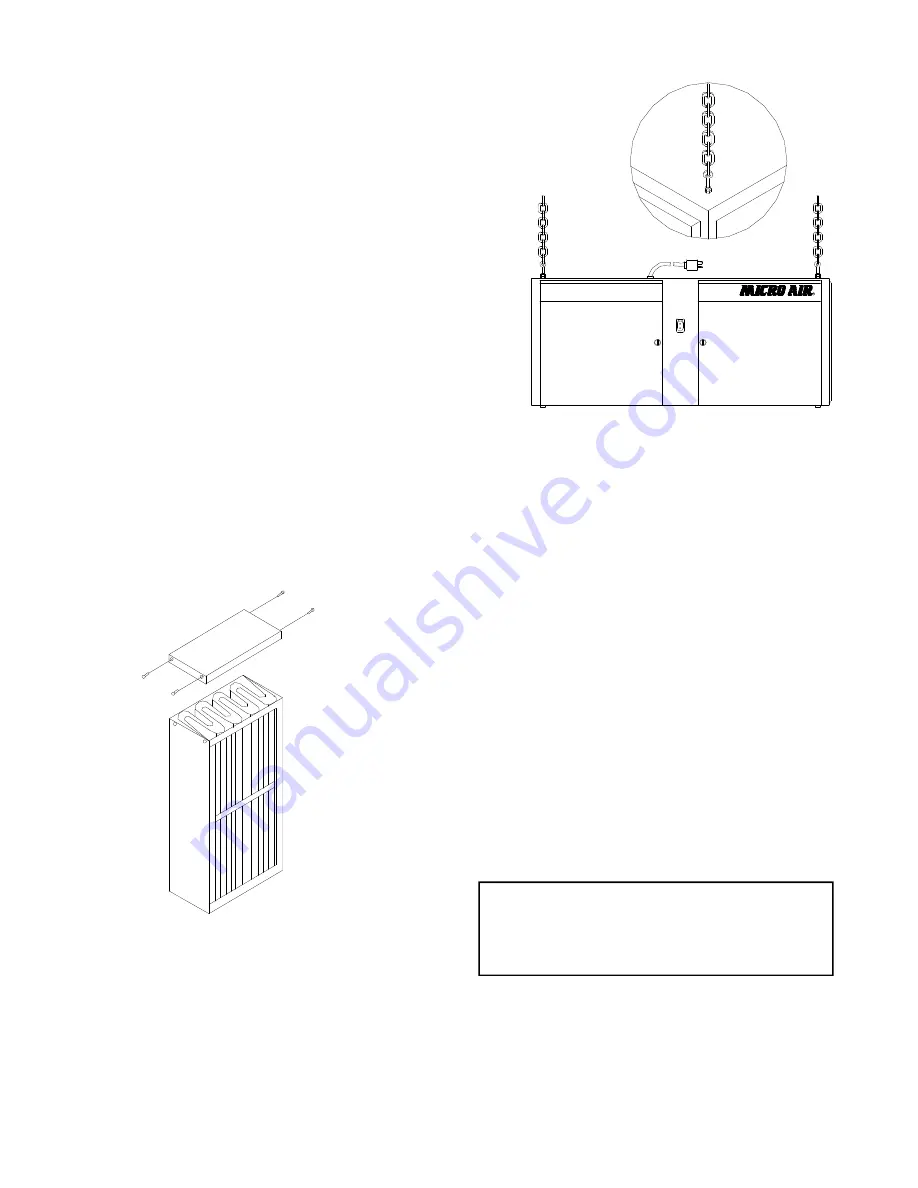
If the unit contains one or two refillable charcoal modules,
(RCM), remove each module from the unit by loosening the
wing bolts that retain the modules, and pulling the module
out. Remove the top cover of RCM to allow acces to fill RCM
with charcoal provided. (See
Fig. 1
.) Replace the top
cover and re-install the modules into the unit, and tighten
wing bolts. (Retain any additional charcoal for future use.)
4.
Replace access doors onto the unit, and tighten latch.
INSTALLATION INSTRUCTIONS
1.
Remove the four (4) 1/4-20 threaded bolts from the corners
located on the top or bottom of the unit. (Note: the MT1251/
MT1252 is designed to work equally well, whether suspended from
the top or bottom.) If the unit is installed upside down, the doors can
be interchanged,so that the logo reads correctly.
2.
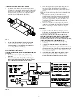
Using the mounting hardware kit provided, screw two (2) hex
nuts onto each eyebolt, then put eyebolt assembly into each
hole from step 1. Tighten the nuts together to prevent loosening
by vibration. The unit is now ready to be installed in an appropriate
location. (See
FIG. 2
.)
FIG. 1
FIG. 2
ELECTRICAL INSTALLATION
CAUTION: DISCONNECT ELECTRICAL POWER BEFORE PROCEEDING
WITH INSTALLATION.
MT1251
1.
Plug power cord into nearst outlet rated at nameplate voltage. Unit is
ready to run.
NOTE:
For Wiring Diagram, see
FIG. 4
.
MT1252
(Above ceiling applications):
1.
A remote wall switch is standard with the MT1252. The unit is installed
by suspending above the ceiling, installing remote switch to nearby
wall, and running wires from the remote switch to the MT1252. Once
wiring is complete, connect name plate voltage to center terminals of
the 2-speed switch. Unit is then ready to run. (See detailed installation
instruction supplied with remote switch kit.)
2.
The muti-speed motor which comes standard with the MT1251/MT1252
can easily be rewired to obtain a variety of air flows. The standard
configuration from the factory is the following:
MOTOR WIRE COLOR
Black (High)
Blue (M/High)
Orange (M/Low)
Red (Low)
Ù
MT1252 High Spd.
Ù
MT 1252 Low Spd.
MT 1251 High Spd.
Ú
MT 1251 High Spd.
Ú
The MT1251 motor speeds can be re-wired by disconnecting the wire
presently to the switch and connecting an alternate wire. For example, to
increase the MT1251 CFM, disconnect the blue motor wire from switch
and connect the black motor wire in its place.
The MT 1252 is direct-wired to motor at the time of installation. Therefore,
you can choose any combination of speeds. Black and orange are the
recommended tap selections. (Refer to remote switch instructions
.)
2
CAUTION: USE WIRE OR CHAIN SUFFICIENT TO SUPPORT THE WEIGHT
OF UNIT (120LBS.). HANG FROM STRUCTURAL SUPPORTS.
NOTE: IF UNIT IS TO BE INSTALLED ON BRACKETS AGAINST A WALL,
USE BRACKETS THAT ARE SUFFICIENT TO HOLD THE UNIT. INSTALL
BRACKETS SECURLY TO THE WALL.

