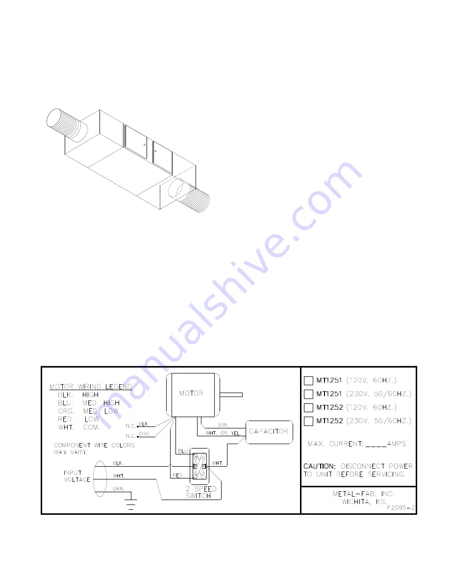
ABOVE CEILING INSTALLATION
1.
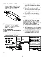
The MT1252 comes standard with a set of rectangular plenums
that include a 14” diameter collar (AM-14) to connect to flexible duct
above ceiling. Upon installing the MT1252, follow the instructions
included with the AM-14 plenum kit. The completed installation
should look like the following diagram. (See
FIG. 3
.)
FIG. 3
2.
As noted in the electrical installation section, use the standard
remote wall switch to control the operation of the MT1252.
Instructions are with kit. (Note: An optional remote switch kit is
available for the MT1251, Kit #34188-01).
FILTER REPLACEMENT
CAUTION: BE SURE UNIT IS OFF OR UNPLUGGED BEFORE
SERVICING.
1.
Remove filter access doors. (Refer to Step 2, Pre-Operating
Instructions)
2.
Remove foam mesh prefilter. Wash prefilter in a mild detergent.
Rinse thoroughly and press excess water from filter using a towel or
cloth. Do likewise with the foam mesh after filter if required.
FIG. 4
3.
When cleaning the prefilter, inspect the HEPA filter(s) if the unit
has one or two filters. (Not applicable with charcoal filters.)
If necessary, replace with new filter(s). See parts list for filter part
number.
NOTE:
The filters may be dust laden, therefore care is suggested during
removal.
4.
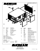
After approximately 6 months use, the refillable charcoal
module(s) will need to be refilled with new charcoal (or activated
alumina). To refill, remove top cover of RCM-6 (retained by four
(4) screws), empty RCM-6 and refill. Shake the RCM-6 to allow
for settling and refill to the top. Replace top cover back onto
RCM-6. (See
Fig. 1
.)
5.
Whenever servicing filter, remember to tighten wing bolts that
retain filters. Once installed, this will insure a total seal against
filter and cabinet flange to eliminate contaminated air bypass.
SERVICE
1.
Always be sure that unit is off before performing any service to
the air cleaner. See wiring diagram attached to the inside of filter
access cover for electrical reference.
CAUTION: THIS PRODUCT DOES NOT CONTAIN INTERLOCK
SWITCHES FOR INTERRUPTION OF POWER TO THE UNIT WHEN
ACCESS COVERS ARE REMOVED. PRIOR TO SERVICING ANY
ELECTRICAL PORTION OF THE AIR CLEANER, DISCONNECT POWER
TO UNIT FROM WALL OUTLET OR BREAKER SWITCH.
2.
Remove filter access doors. (Refer to Step 2, Pre-Operating
Instructions.)
3.
To service filters, follow steps outlined in Filter Replacement
Instructions.
4.
If motor or blower requires servicing, remove from unit. The blower is
secured to cabinet by four (4) 5/16” hex nuts. Disconnect motor wires
from unit and remove 5/16” hex nuts so that motor/ blower assembly
can be removed from the unit.
5.
Upon repairing motor/ blower assembly (see parts list for motor
and blower part numbers) install into unit. Reconnect motor
wires and secure blower to cabinet using the 5/16” hex nuts.
3

