2
MODEL OM550DD SPECIFICATIONS
Input Volts:
120 VAC, Single Phase
230 VAC, Single Phase
208-230/460 VAC, 3 Phase
Max. Current:
1/2 HP 120 VAC
7.6 AMPS
1/2 HP 230 VAC
3.8 AMPS
1/2 HP 208/230/460 VAC 2.6/2.0/1.0 AMPS
3/4 HP 120 VAC
10 AMPS
3/4 HP 230 VAC
5 AMPS
3/4 HP 208/230/460 VAC 2.8-2.4/1.2 AMPS
Motor:
1/2 HP TEFC Single Phase
1/2 HP TEFC 3-Phase
3/4 HP TEFC Single Phase
3/4 HP TEFC 3-Phase
Air Flow*:
6” inlet 450CFM (1/2 HP Motor)
6” inlet 600CFM (3/4 HP Motor)
Dimensions:
31 3/8” H x 20” W x 14” D (less Brackets)
40” H x 20” W x 14” D (with Brackets)
Shipping Weight: 136 lbs.
Actual Weight:
116 lbs.
*All airflows are tunnel-tested readings.
PACKAGE CONTENTS
1ea.
OM550DD Unit
2ea.
Machine Mount/Hangar Brackets
1ea.
Owner’s Manual
PRE-OPERATING INSTRUCTIONS
1. Remove OM550DD unit and mounting brackets (not
assembled) from crate packaging.
2. Inspect unit for shipping damage and report any damage
to freight carrier.
INSTALLATION INSTRUCTIONS
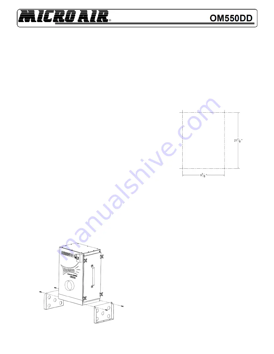
A. MACHINE MOUNT / FLOOR MOUNT
1.
Remove two 5/16” bolts from each side of cabinet
near the bottom of the unit
FIG.1
2. Use the bolts removed in Step 1 to secure Machine
Mounting brackets to unit as shown in
FIG.1
.
3. Locate an installation site that will provide for the
following:
A solid structure capable of supporting the weight
of the unit.
Three feet of unobstructed exhaust space from
the outlet of the unit.
Easy access to service panels and unit inlet. As
near as possible to the source of the oil mist unit
to be captured.
4. Mark location of the mounting holes on the surface to
which unit is to be mounted, (see
FIG.2
for hole
pattern). Drill or punch holes that are sized for
mounting hardware to be used.
FIG.2
5. Lift OM550DD unit onto machine, aligning machine
mount brackets over mounting holes previously
drilled. Secure to machine using standard bolts, nuts
and lock washers.
CAUTION: The size and weight of the OM550DD requires
two persons or mechanical means to lift and hold during
mounting
.
6. Connect unit to oil mist source using a duct having the
same diameter as the inlet of the unit. The duct may
be flexible hose or formed sheet metal. Maximum flow
will be obtained with minimum bends in duct. To
contain oil that will collect on the inside of the duct,
the duct must be sealed. Use hose clamps or sheet
metal screws to attach duct to unit.
B. CEILING MOUNTING
NOTE:
The Machine Mount/Hangar Brackets used in Section
A may be used for suspension mounting purposes.
1.
Remove the two 5/16” bolts from each side of the
cabinet at the outlet end.
2. Use the bolts removed in Step 1 to secure the ceiling
mount brackets to the unit as shown in
FIG.3
.
3.
Locate an installation site that will meet the
requirements listed in Step 3 of the machine mounting
instruction.
Summary of Contents for OM550DD
Page 5: ...5 FIG 5 ...

