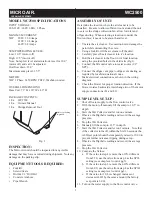
MODEL WC2500 SPECIFICATIONS
INPUT VOLTAGE:
208-230V / 460V 60Hz 3 Phase
MAXIMUM CURRENT:
5HP
208V: 13.6 Amps
230V: 12.4 Amps
460V: 6.2 Amps
SUMP OPERATING LEVELS:
Low: 10.5” (motor off)
High: 11.5” (motor off)
Note: Sump low level alarm interlock is set for 10.0”
(motor off) and can’t be adjusted.
Overfl ow drain: 13.0”
Maximum sump level: 15.5”.
MOTOR:
5HP 3 Phase 3450 RPM TEFC, Washdown rated
OVERALL DIMENSIONS:
Base Unit: 73” H x 36” W x 49” D
PACKAGE CONTENTS:
1 Ea.
WC2500
1 Ea.
Owners Manual
1 Ea.
Sludge Removal Tool
INSPECTION:
The Micro Air unit should be inspected for any visible
damage that may have occurred during shipment. Note any
damage on the packing slip.
EQUIPMENT/TOOLS REQUIRED:
•
Forklift
•
Screwdrivers
•
Drill & 1/2” Drill Bit
•
Concrete Anchors
•
Pipe Wrench
ASSEMBLY OF UNIT:
Determine the location where the air cleaner is to be
installed. Be sure to allow suffi cient room around the unit
to service the sludge collection bin, allow for inlet and
offgas ducting. When selecting a location consider the
fl oor surface; it needs to be smooth and level.
1. Uncrate the air cleaner. Use caution not to damage the
paint while dismantling the crate.
2. Using a forklift, lift the air cleaner off the skid.
3. Carefully place the air cleaner into it’s location.
4. Bolt the air cleaner to the fl oor in it’s fi nal location
using the provided holes in the skid rails (Fig 1).
5. Connect the fi ll control valve to water source (1/2”
NPT).
6. Connect the offgas vent pipe to offgas vent ducting as
required by local/state/national codes.
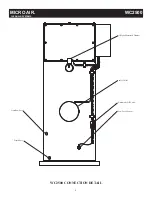
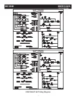
7. Make electrical connections as shown in the wiring
diagram.
8. Check the blower for proper rotation direction. If the
blower rotates backwards, interchange two of the motor
supply connections (L1 and L2)
SUMP LEVEL SET-UP:
1. Shut off water supply to the fl ow control valve.
2. With the motor off manualy fi ll the sump to 10.5” in
depth.
3. Start the Wet Collector and let run one minute.
4. Observe the Digihelic reading and record the average
pressure.
5. Stop the Wet Collector.
6. Manualy fi ll the sump to 11.5” in depth.
7. Start the Wet Collector and let run 1 minute. Note that
if the collector turns off within the fi rst 20 seconds the
ALHI set point should be temporarily raised to 10.00 to
prevent further nuisance tripping during set up.
8. Observe the Digihelic reading and record the average
pressure.
9. Stop the Wet Collector.
10. Compare the Values:
a. If the value in step 4 is more than 10% different
from 2.50, use the value from step 4 as the SP1L
setting (see sump level control pg 3).
b. If the value in step 8 is more than 10% different
from 4.00, use the value from step 8 as the SP1H
setting (see sump level control pg3).
c. If the value for 10.b is changed, increase or
decrease ALHI by the same amount (the factory
set-point is 6.00).
11. Turn on the water supply to the fl ow control valve.
Fig. 1
MICRO AIR
®
WC2500
CLEAN AIR SYSTEMS
Holes for bolting
to ground.
2


