Page 47
Outputs and Inputs
thermoMETER CT
8.2.4.2 Commissioning Profibus
Read in the „IT010A90.gsd“ GSD file, contained on the delivered CompactConnect software CD, into the
PLC configuration tool and configure the controller.
At least one module must be selected. You will find more information about the Profibus interface on the
enclosed CompactConnect software CD, page 18.
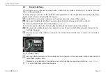
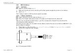
Open the controller and connect the power supply
Connection
Profibus cable
Power supply
GND
+8 up to +36 VDC
Sensor cable
Fig. 19 Commissioning Profibus
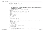
Switch on the power supply.
Press the Mode button 18 times until the item
SL001
appears. Set the slave address with the
UP
and
DOWN
buttons. Valid slave addresses start with 001 up to 125. Use the same address as in the PLC con-
figuration tool, see the Profibus instruction manual on page 4, 6 on CompactConnect Software CD.
Switch off the controller for at least 3 seconds by interrupting the power supply.
Connect the connector of the Profibus cable with a Profibus port. Take care on the terminating resistor of
the Profibus.
The controller with DPv1 Profibus is now ready for data exchange with the Profibus master; see the Profibus
instruction manual on page 7 on CompactConnect Software CD.
The measuring values are displayed in hex format and must be converted into decimals; see the Profibus
instruction manual on page 7 on CompactConnect Software CD.
The settings of the DPv1 Profibus interface and the communication with the Profibus master are described in
the Profibus instruction manual on CompactConnect Software CD.

