Page 44
Installation and Assembly
induSENSOR DTD / MSC7xxx
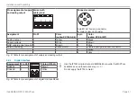
Assignment
Pin X2-x
LDR-x-CA
LVP-25-Z20-x
Cable
C7210-x
Secondary center tap
1
White
White
Sec
2
Brown
Black
Secondary -
3
Green
Green
P
4
Yellow
Yellow
Primary -
5
Gray
Gray
Cable shield sensor 1 + 2, see X1 and X3
Fig. 45 Table for pin assignment sensor 1 + 2 (LDR)
i
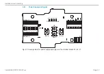
Cable lengths ≥ 10 m between sensor and controller may impair the technical data
.
4.6.3
Digital Interface
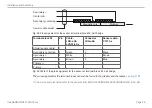
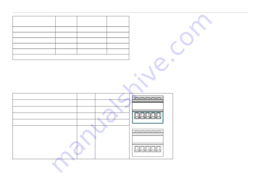
Assignment
Pin X3
Color (IF7001)
X3
X2-1
1 2 3 4 5
1 2 3 4 5
i
Do not apply the IF7001 shield!
A (RS485)
1
Brown
B (RS485)
2
White
-
3
-
-
4
-
Cable shield sensor 1
(direct connection to DIN rail)
5
-
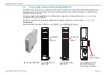
Fig. 46 Table for pin assignment of digital interface X3


