Page 17
Installation and Assembly
MSC7401 Miniature sensor controller for inductive sensors
4.3.1
Power Supply and Signal
X2
1
2
3
4
1
2
1
2
3
4
5
6
X1
X3
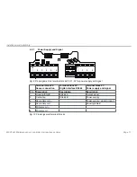
Fig. 9 Pin assignment on terminal blocks X2, X1, X3 for power supply and signal
Terminal block X2:
Sensor connection
Terminal block X3:
Digital interface RS485
Terminal block X1:
Power supply and signal
Pin
Description
Description
Description
1
Housing/Shield
RS485 A
Output signal
2
Center tap
RS485 B
Power supply
3
Secondary coil +
Power supply / signal ground
4
Secondary coil -
Housing/Shield
5
Primary coil +
6
Primary coil -
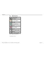
Fig. 10 Pin assignment terminal blocks


