Page 18
Installation and Assembly
MSC7401 Miniature sensor controller for inductive sensors
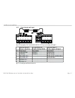
Pin assignment power supply and signal
1
2
3
4
5
View on connector side
Pin
Description
1
Power supply
2
Analog output channel 2 (if available)
3
Power supply and signal ground
4
Analog output channel 1
5
Not used
Fig. 11 Pin assignment power supply and signal, connector M12x1; 5 pole; A coded
4.3.2
Sensor
If the plunger is moved into the sensor, this results in an increase of the output voltage, if the plunger is pulled
out further, this results in a decrease of the output signal. Change the inputs sec+ and sec- if the output sig-
nal should decrease when the plunger is moved in.
Pin assignment Sensor
1
2
3
4
5
View on solder pin side
Pin
Description
1
Sec
2
Secondary -
3
P
4
Primary -
5
Secondary medium tab
Fig. 12 Pin assignment sensor, female connector M9, 5 -pole. series 712, Fa. Binder

