Page 32
Operation
MSC7401 Miniature sensor controller for inductive sensors
5.4.4
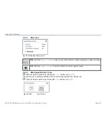
Example B: Signal Output Adjustment: 2 ... 10 V
D1
D2
D3
D4
G
MENU
Press the
MENU
button for 3 seconds
,
if you are not yet in the menu.
G
R
G
Output situation: The sensor parameters are already set; depending on the approach, LED
D4
is
green or switched off.
G
O
G
Menu point: Signal, see Chap.
5.3.2
; in delivery state, the electronics works with automatic load
recognition; depending on the output load, the LED
D4
is red (4 ... 20 mA) or orange (2 ... 10 V).
If the automatic settings suits you, you can cancel example B here.
ENTER
Confirm by pressing the
ENTER
button.
G
O
G
G
O
O
Voltage output
ENTER
Confirm by pressing the
ENTER
button.
G
O
O
O
2 ... 10 V; with
the selection can be changed here.
ENTER
Confirm by pressing the
ENTER
button.
G
R
G
Output situation: The sensor parameters are already set; depending on the approach, LED
D4
is
green or switched off.


