Adjustment and Maintenance
4
4.5.3.2.4.REMOTE
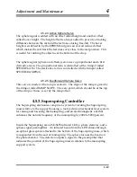
The Superspring can be made to zero using an external TTL signal.
4.5.3.2.5.MANUAL
In manual mode, the spring motor is controlled by the potentiometer (pot) on
the front panel. A setting greater than 5 will move the spring up less than 5
will lower the spring. Moving the spring up will case the BNC Sphere out to
move in a positive direction while down will move voltage output in a
negative direction.
4.5.3.3.Active Servo
The
filter is a band pass accomplished with a high pass (HP) and then a low
pass (LP) filter. The Q-value and frequency of each filter is adjustable via the
on-board trim pots. The phase lead and lag and the servo gain are also
adjustable.
4.5.3.4.Coil Drive (Current Driver)
The filter section feeds the coil driver which produces a current for the coil
using a high power op amp. The signal feeding the coil driver can be viewed
at COMP OUT. The signal returning from the coil can be monitored at COIL.
The coil driver can be engaged with the COIL switch. You can also insert a
signal to the coil at the Noise Inject BNC on the back panel.
4-43
2
Nelson P.G.,
An Active Vibration Isolation System for Inertial Reference and Precision
Measurement
, Rev. Sci. Instrum., 1991,
62
, 2069-2075.
Summary of Contents for FG5
Page 22: ...Design Components and Function 2 Figure 2 10 The Superspring 2 14 ...
Page 31: ...Design Components and Function 2 Figure 2 13 Rotation Monitor 2 23 ...
Page 32: ......
Page 42: ...How to Set Up and Run the FG5 3 3 10 ...
Page 44: ...How to Set Up and Run the FG5 3 Figure 3 2 V Post 3 12 ...
Page 53: ...How to Set Up and Run the FG5 3 1 Backup the data 2 Shut off computer power 3 21 ...
Page 87: ...Adjustment and Maintenance 4 4 29 ...
Page 91: ...Adjustment and Maintenance 4 4 33 ...
Page 104: ...Troubleshooting 5 5 2 ...
Page 117: ...Troubleshooting 5 5 15 ...
Page 131: ...Checklists and Logs Appendix D 9 3 ...
Page 140: ...Checklists and Logs Appendix D Table 9 6 Replacing Drive Belt 9 12 ...
Page 145: ...Checklists and Logs Appendix D Table 9 10 Replace Linear Bearings 9 17 ...
Page 149: ...Checklists and Logs Appendix D Table 9 13 Replace Shaft Encoder 9 21 ...


