Checklists and Logs
Appendix D
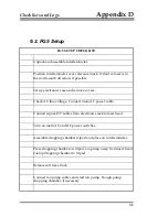
Connect three cables to the dropping chamber: Vacuum
feedthrough (white Lemo), motor cable (orange Lemo), shaft
encoder (blue Lemo).
Connect BNC from temperature probe on tripod tray to BNC 16 1H.
Connect Superspring cable.
Connect APD power (green Lemo).
Connect BNC fringe signal to interferometer TTL port and front
panel of Scaler/Counter.
Recheck beam verticality. Adjust if necessary.
Adjust Superspring zero position.
Record Superspring sphere voltage in system check log.
Close Superspring servo loop (turn coil switch on).
Put Dropper in OSC mode and hit RESET then INIT to make the
dropper move smoothly up and down.
Optimize fringe signal.
9-6
Summary of Contents for FG5
Page 22: ...Design Components and Function 2 Figure 2 10 The Superspring 2 14 ...
Page 31: ...Design Components and Function 2 Figure 2 13 Rotation Monitor 2 23 ...
Page 32: ......
Page 42: ...How to Set Up and Run the FG5 3 3 10 ...
Page 44: ...How to Set Up and Run the FG5 3 Figure 3 2 V Post 3 12 ...
Page 53: ...How to Set Up and Run the FG5 3 1 Backup the data 2 Shut off computer power 3 21 ...
Page 87: ...Adjustment and Maintenance 4 4 29 ...
Page 91: ...Adjustment and Maintenance 4 4 33 ...
Page 104: ...Troubleshooting 5 5 2 ...
Page 117: ...Troubleshooting 5 5 15 ...
Page 131: ...Checklists and Logs Appendix D 9 3 ...
Page 140: ...Checklists and Logs Appendix D Table 9 6 Replacing Drive Belt 9 12 ...
Page 145: ...Checklists and Logs Appendix D Table 9 10 Replace Linear Bearings 9 17 ...
Page 149: ...Checklists and Logs Appendix D Table 9 13 Replace Shaft Encoder 9 21 ...


