Adjustment and Maintenance
4
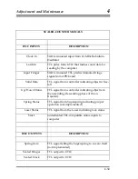
The LED driver supplies a constant current to drive the LED in the
Superspring can. This current can be adjusted internally using the
potentiometer (pot).
The sphere signal buffer buffers the signal from the Superspring can so it can
be routed to different parts of the board. The Sphere Detector Out BNC can
be low pass filtered at 1.26 Hz (FILTER ON).
The window comparator checks the LP-filtered sphere signal to see if it is
within the preset range.
If the signal is within the window the Range Status
will be "High;" if the signal is out of the window the Range Status will be
"Low."
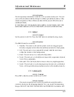
4.5.3.2.MOTOR DRIVE SELECTION
The motor driver circuit can be selected by an external switch with five
positions: OFF, WINDOW, AUTO, REMOTE, and MANUAL. This controls a
DC motor which can position the top of the main spring relative to the main
bracket. The position may need to be adjusted as the main spring slowly
stretches over time, or due to temperature or gravity changes. The DC motor
can lift (lower) the test mass so that the sphere position becomes more
positive (negative). This motor should only be used to position the mass but
should not be activated during the Superspring operation as a long period
isolation device.
4.5.3.2.1.OFF
This setting disables the DC motor that positions the top of the main spring.
The Superspring should be left in this mode when the active servo is
activated.
4.5.3.2.2.AUTO
The Superspring controller will try drive the DC motor using a feedback loop
so that the sphere signal is zero.
4.5.3.2.3.WINDOW
4-42
The Superspring controller will activate the motor when the sphere voltage is
out of range (larger than the window setting). The motor drives the sphere
voltage to zero and then is turned off. In principal the Superspring can be left
in this mode but it could re-zero during a measurement causing excess noise.
Summary of Contents for FG5
Page 22: ...Design Components and Function 2 Figure 2 10 The Superspring 2 14 ...
Page 31: ...Design Components and Function 2 Figure 2 13 Rotation Monitor 2 23 ...
Page 32: ......
Page 42: ...How to Set Up and Run the FG5 3 3 10 ...
Page 44: ...How to Set Up and Run the FG5 3 Figure 3 2 V Post 3 12 ...
Page 53: ...How to Set Up and Run the FG5 3 1 Backup the data 2 Shut off computer power 3 21 ...
Page 87: ...Adjustment and Maintenance 4 4 29 ...
Page 91: ...Adjustment and Maintenance 4 4 33 ...
Page 104: ...Troubleshooting 5 5 2 ...
Page 117: ...Troubleshooting 5 5 15 ...
Page 131: ...Checklists and Logs Appendix D 9 3 ...
Page 140: ...Checklists and Logs Appendix D Table 9 6 Replacing Drive Belt 9 12 ...
Page 145: ...Checklists and Logs Appendix D Table 9 10 Replace Linear Bearings 9 17 ...
Page 149: ...Checklists and Logs Appendix D Table 9 13 Replace Shaft Encoder 9 21 ...


