Design: Components and Function
2
The Rubidium Oscillator is an atomic resonance-controlled oscillator or
equivalent which outputs a stable sinusoidal signal of 10 MHz.
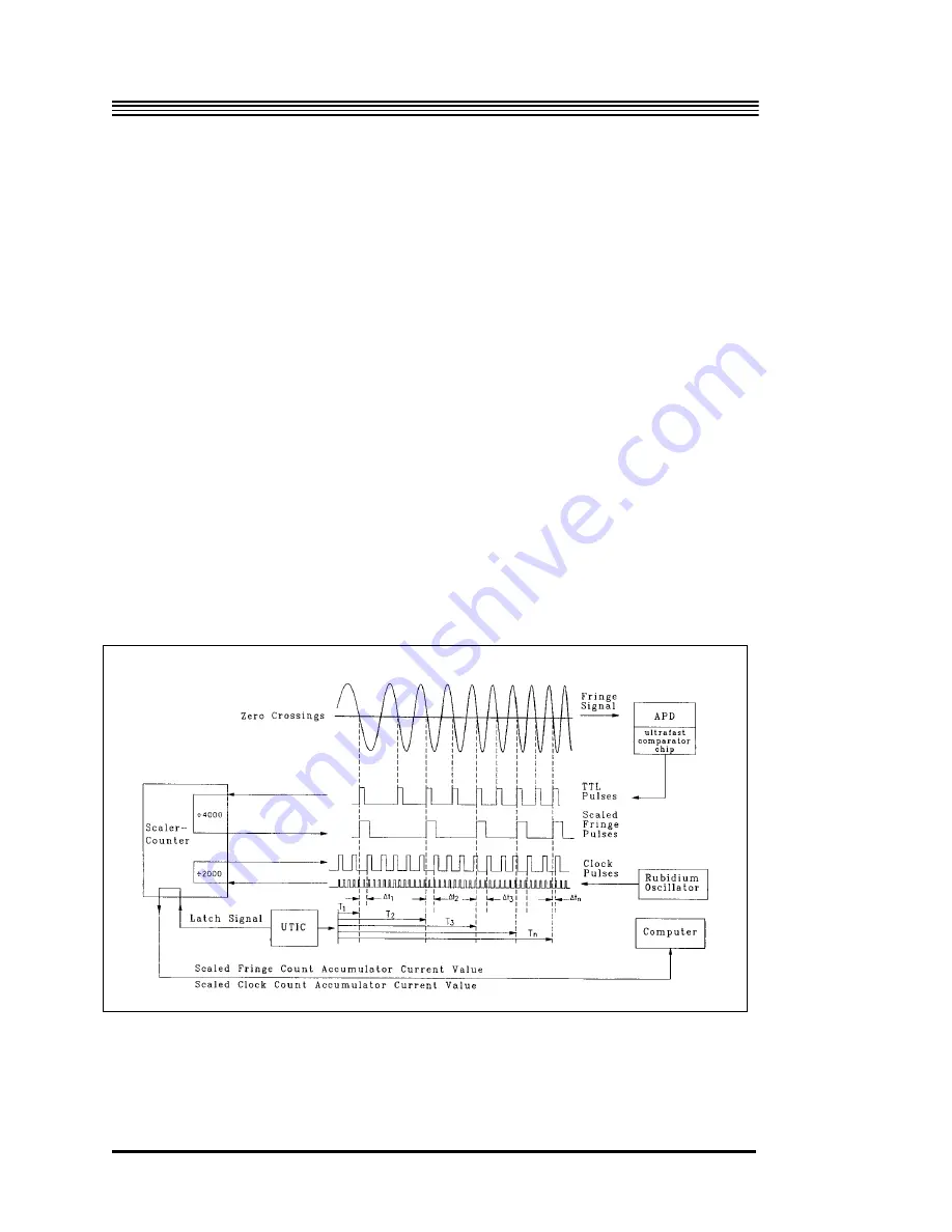
The Universal Time Interval Counter (UTIC) measures the time interval
between the occurrence of each scaled fringe and the next scaled clock pulse.
Using this information, the system controller computes the absolute time of
occurrence of the scaled fringes.
The Scaler Counter uses a zero-crossing discriminator to transform the
sinusoidal signals from the rubidium oscillator to square wave (TTL) pulses.
It keeps track of the number of fringes that have passed by counting the TTL
signals from the APD. It also scales (divides) the fringes and the 10 MHz TTL
clock pulses by user-defined scale factors. Nominal scale factors are 4000 for
fringes and 2000 for clock pulses. Both scale factors are “hard set” by
switches on the scaler counter circuit board.
Figure 2-12
Timing diagram
2-18
Summary of Contents for FG5
Page 22: ...Design Components and Function 2 Figure 2 10 The Superspring 2 14 ...
Page 31: ...Design Components and Function 2 Figure 2 13 Rotation Monitor 2 23 ...
Page 32: ......
Page 42: ...How to Set Up and Run the FG5 3 3 10 ...
Page 44: ...How to Set Up and Run the FG5 3 Figure 3 2 V Post 3 12 ...
Page 53: ...How to Set Up and Run the FG5 3 1 Backup the data 2 Shut off computer power 3 21 ...
Page 87: ...Adjustment and Maintenance 4 4 29 ...
Page 91: ...Adjustment and Maintenance 4 4 33 ...
Page 104: ...Troubleshooting 5 5 2 ...
Page 117: ...Troubleshooting 5 5 15 ...
Page 131: ...Checklists and Logs Appendix D 9 3 ...
Page 140: ...Checklists and Logs Appendix D Table 9 6 Replacing Drive Belt 9 12 ...
Page 145: ...Checklists and Logs Appendix D Table 9 10 Replace Linear Bearings 9 17 ...
Page 149: ...Checklists and Logs Appendix D Table 9 13 Replace Shaft Encoder 9 21 ...


